
Installation Guide

6
WARRANTY
For more eective and safer operation and to
prolong the life of the heater, read the Owner’s
Guide and follow the instructions. Failure to
properly maintain the heater will void any warranty
and may cause the heater to function improperly.
LIMITED FIVE YEAR WARRANTY: Cadet will re-
pair or replace any Cadet Register (RM) heater
found to be defective within five years after the
date of purchase.
These warranties do not apply:
1. Damage occurs to the product through improper
installation or incorrect supply voltage;
2. Damage occurs to the product through
improper maintenance, misuse, abuse, accident,
or alteration;
3. The use of unauthorized accessories or unau-
thorized components constitutes an alteration and
voids all warranties. Refer to Cadet website or call
customer service at 855.CADET.US for list of
authorized accessories and components.
4. CADET’S WARRANTY IS LIMITED TO
REPAIR OR REPLACEMENT.
5. IN THE EVENT CADET ELECTS TO REPLACE
ANY PART OF YOUR CADET PRODUCT, THE
REPLACEMENT PARTS ARE SUBJECT TO
THE SAME WARRANTIES AS THE PRODUCT.
THE INSTALLATION OF REPLACEMENT PARTS
DOES NOT MODIFY OR EXTEND THE UN-
DERLYING WARRANTIES. REPLACEMENT OR
REPAIR OF ANY CADET PRODUCT OR PART
DOES NOT CREATE ANY NEW WARRANTIES.
If you believe your Cadet product is defective,
please contact Cadet during the warranty period,
for instructions on how to have the repair or
replacement processed.
Parts and Service
Visit cadetheat.com/parts-service for information
on where to obtain parts and service.
INSTALLATION INSTRUCTIONS
To register your product, visit cadetheat.com/product-registration
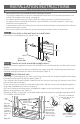
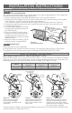
1. Route the electrical supply wire from the circuit breaker to the wall thermostat. At the wall can of
heater #1, remove two knockouts and attach two sets of electrical supply wires with two cable
clamp connectors (not included) leaving a minimum of 6 inches wire lead. One set of electrical
supply wire goes to the wall thermostat and the other set goes to heater #2 (See Figure 8).
2. There are two supply ground wires in the wall can of heater #1 (See Figure 7). Connect the green
ground wire in the wall can of heater #1 to each of the ground wires from each set of the supply
wires (See Figure 7).
3. For heater #1, connect each heater wire to one of the supply wires going to the thermostat, and
one of the supply wires going to the heater #2. Each of the wires from heater #1 must have a
3-wire connection.
RESET
See Instructions
RESET
See Instructions
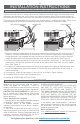
MULTIPLE HEATERS WITH ONE THERMOSTAT
4. For heater #2, make the connections in the wall can as shown in Figure 8 above.
5. Turn power back on at the main disconnect panel.
6. Proceed to OPERATING INSTRUCTIONS.
Figure 8 Heater #2
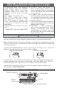
More than one heater can be wired in parallel on the same circuit breaker (be sure to check
national and local codes for safety requirements). Additional electrical supply wire and cable clamp
connectors are required, and you’ll need to use a wall thermostat. When wiring multiple heaters to
one thermostat, the heaters must be in the same room and be spaced a minimum of three feet apart.
The maximum amperage load you can put on one circuit breaker is limited to either 80% of the circuit
breaker capacity, or the maximum amperage rating of the thermostat, whichever is lower.
Figure 7 Heater #1
RESET
See Instructions
RESET
See Instructions
to the wall thermostat to heater #2 from heater #1