
Installation Guide

6
WARRANTY
For more eective and safer operation and to
prolong the life of the heater, read the Owner’s
Guide and follow the instructions. Failure to prop-
erly maintain the heater will void any warranty and
may cause the heater to function improperly.
LIMITED LIFETIME WARRANTY: Manufactur-
er will repair or replace any Electric Baseboard
(F) heater found to be defective at any time.
These warranties do not apply:
1. Damage occurs to the product through improp-
er installation or incorrect supply voltage;
2. Damage occurs to the product through improp-
er maintenance, misuse, abuse, accident, or al-
teration;
3. The use of unauthorized accessories or unau-
thorized components constitutes an alteration and
voids all warranties. Refer to Manufacturer web-
site or call customer service at 888.346.7539 for
list of authorized accessories and components.
4. Manufacturer’s warranty is limited to repair or
replacement.
5. In the event Manufacturer elects to replace
any part of your product, the replacement parts
are subject to the same warranties as the prod-
uct. The installation of replacement parts does not
modify or extend the underlying warranties. Re-
placement or repair of any product or part does
not create any new warranties.
If you believe your product is defective, please
contact Manufacturer during the warranty period,
for instructions on how to have the repair or
replacement processed.
Parts and Service
Visit gdaheat.com/parts for information on where
to obtain parts and service.
To register your product, visit gdaheat.com/register
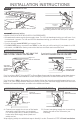
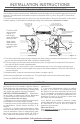
Figure 11
A. Two sets of electrical supply wire go through two cable clamp connectors of baseboard #1. One set
goes to the thermostat and the other set goes to baseboard #2.
B. The two supply ground wires need another short piece of copper wire to make the 3-wire connec-
tion with the ground screw in baseboard #1.
C. For baseboard #1, connect each of the cut baseboard wires to one of the supply wires going to
the thermostat, and one of the supply wires going to the other baseboard. They both must have a
3-wire connection.
For baseboard #2, make the connections as shown on pages 4 and 5.
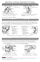
MULTIPLE BASEBOARD HEATERS WITH ONE THERMOSTAT
DO NOT
CUT!
note: two sets of
electrical supply wire
going into this baseboard
from heater #1:
a black, white
and ground
(inset)
baseboard #1baseboard #2
to the wall thermostat:
a black, white and
ground
Multiple baseboard heaters can be wired in parallel on the same circuit breaker (check national and
local codes for safety requirements). Additional electrical supply wire and cable clamp connectors are
required. The thermostat and heaters must be in the same room. If you’re using a BTF, follow those
instructions.
The maximum amperage load you can put on one circuit breaker is limited to either 80% of the circuit
breaker capacity, or the maximum amperage rating of the thermostat, whichever is lower.
For 240 or 208
volts pictured
(Figure 11),
both supply
wires (black and
white) are hot.
Wrap supply
(white) wires
with black tape
to identify them
as hot.
Screw wiring compartment covers back on. Turn power back on at the main disconnect panel.
Proceed to OPERATING INSTRUCTIONS.
C
A
B
A
C
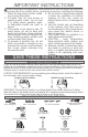
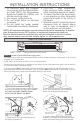
INSTALLATION INSTRUCTIONS