
User manual

T1 or E1 selection is done on the y and does not require any hardware upgrades.
PRI ports are equipped with a standard RJ45 jack for T1 or balanced E1 connection.
6.1.1 RJ48/45 pin-out for T1/E1/PRI module
PSTN simulator is equipped with a two standard RJ45 jacks for PRI ports and connects
to a PRI end-devices with straight shielded CAT3 or CAT5 twisted pair cable.
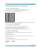
Following cable pin-out is being used at the simulator side:
Pin Description
1 RX Tip
2 RX Ring
3 RX SHIELD
4 TX TIP
5 TX RING
6 TX SHIELD
7 Not used
8 Not used
Note: For connecting PSTN simulator to a Cisco router with a balanced 120-ohm E1/PRI interface with a DB15
connector you need to use Cisco cable P/N: CAB-E1-PRI/NT
6.1.2 LEDs description for T1/E1/PRI module
Each PRI port have two integrated LEDs: Left LED is Yellow and Right LED is Green.
When Yellow (left) LED is ON, it indicates that a Remote (Yellow) alarm is present.
When Green (right) LED is ON it indicates that the interface in activated.
When Green (right) LED is blinking, it indicates that one or more calls are active on that port.
6.2 Conguring T1/E1/PRI module
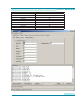
When PRI module is installed your ISDN Manager will display two additional tabs for conguring
T1, E1 and PRI parameters.
6.2.1 Interface type: T1 or E1
First step in conguring PRI call switching is interface type selection. PRI module supports full T1 or full E1
operation. Default is T1.
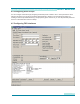
6.2.2 Line Code and Framing
There are several different linecodes and framings available for T1 or E1 interfaces
Linecode for T1: AMI, B8ZS
Framing for T1: SF, ESF
27
User Manual
Public Switched Telephone Network (PSTN) Simulators