
Specifications

- 58 -
AS/CA S002:2010 COPYRIGHT
OCTOBER 2010
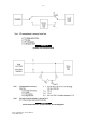
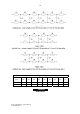
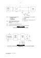
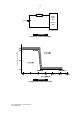
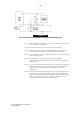
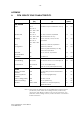
FIGURE 27
Test circuit for measurement of longitudinal power level
Note 1: If the equipment has separate protective and signal earth terminals
they are connected together.
Note 2: The two resistors R1 are to be matched to within 0.01%.
Note 3: The measuring instrument is of high impedance, and capable of
measuring over the frequency range 3.4 kHz to 30.175 MHz.
Note 4: The measuring instrument is calibrated in dBm as if it was measuring
across a resistive load.
Note 5: The adequacy of the balance is checked by repeating
measurements with appropriate connection reversal, or equipment
disconnection.
Note 6: The value of the resistors R1 and R2 are to be 70 Ω for CE signals with
fundamental frequency components in the 3.4 kHz to 30.175 MHz
range when the CE is not being tested with any associated
equipment.
Note 7: If required, blocking capacitors with a value of 4uF may be placed
in series with each R1 resistor during the idle, hold or ringing states.
Variations of this arrangement are permitted if necessary for correct
operation of the CE, but must be carefully considered to ensure
correct longitudinal power level measurements.
(Note 7)