
Specifications
- 41 -
AS/CA S002:2010 COPYRIGHT
OCTOBER 2010
Note 2: In practice, when measuring sustained signals from modems or
similar devices, it may be convenient to observe the indication of
the square-law detector and then to calculate the one-minute
mean value.
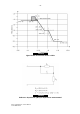
6.7.9.4 For determining the measurement of peak to peak voltages
required by Clause 5.4.2.2 a storage oscilloscope with a minimum
bandwidth of DC to 10 MHz should be used in place of the spectrum
analyser in the test circuit shown in Figure 23.
6.7.9.5 Power Spectral Density should be measured using the following:
(a) A 10 kHz noise power bandwidth for frequencies between
3.4 kHz and 30.175 MHz.
(b) A 1 MHz noise power bandwidth for frequencies between
300 kHz and 30.175 MHz as described in Clause 5.4.2.4.2.
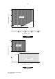
6.7.10 Two-wire physical ring-in/loop-out PSTN line interface seizure
and hold states
6.7.10.1
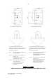
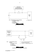
The DC conditions in the Seizure and Hold States on ring-in/loop-out
PSTN lines, as specified in Clauses 5.5.1.4 and 5.5.1.5, should be
tested using the circuits of Figure 1 and Figure 2.
6.7.10.2 The DC conditions of the Seizure State should be measured at
300 ms after the transition to the low resistance (ON-LINE State)
determined in Figure 1.
6.7.10.3 The Hold State condition should be measured after DC current has
reached its steady state.
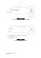
6.7.11 Decadic signal generation and reception
6.7.11.1
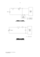
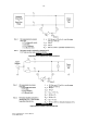
The test configurations for decadic signalling should be as shown in
Figure 11 and Figure 12. Figure 11 indicates the test configuration
which should be used to measure pulse timing and the resistance
during transmission. Figure 12 indicates the test configuration which
should be used to measure the pulse voltage waveshape.
6.7.11.2 When testing for compliance with Clause 5.5.1.8(b)(ii) for the
resistance during the break period, a 100 V d.c. source should be
used in the test configuration as shown in Figure 11.
6.7.11.3 For timing measurements, a 48 V d.c. source should be used in the
test configuration as shown in Figure 11.
6.7.12 Supervisory tone measurement
Supervisory tones should be measured using the test circuit of
Figure 23 with a waveform recorder in place of the spectrum
analyser.