
Specifications
- 40 -
AS/CA S002:2010 COPYRIGHT
OCTOBER 2010
6.7.7.2.2 Transverse impedance should be tested using the test configuration
of Figure 13.
6.7.8 DTMF signal sending
6.7.8.1
DTMF levels and DTMF signal timing should be measured using a
suitable waveform recorder and signal processor.
6.7.8.2 The main frequencies and levels should be measured using the test
circuit shown in Figure 21 and Figure 22.
6.7.8.3 Distortion should be measured at the CE using the test circuit shown
in Figure 21, but with the artificial line set to 0 km length.
Note: It is recommended that the DTMF measuring instruments should be
switched to a bandwidth of 10 Hz for selective measurements.
6.7.9 Signal levels and frequencies
6.7.9.1
Signal levels and frequencies should be measured as shown in
Figure 23 using a selective level meter or spectrum analyser with
appropriate input dynamic range and frequency range. When used
to measure the levels of individual frequency components,
bandwidths of 3 Hz, 10 Hz, 30 Hz and 100 Hz may be used as
appropriate.
6.7.9.2 Power levels specified in Clause 5.4.2 should be determined as V2/R,
the voltage level being measured with a high impedance RMS
voltmeter bridged across R, the termination resistor (nominally 600 Ω
unless otherwise specified).
6.7.9.3 For the one-minute mean power level measurements the voltmeter
should have the following elements:
(a) An input band-selection filter with passband 300 Hz to 3.4 kHz.
(b) A square-law detector having a time constant of 100 ms
nominally.
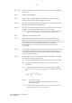
(c) An averaging circuit that performs a continuing averaging
process over a period of one minute, i.e. computes the value
of:
1/60
∫
T
n
+ 60
V
2
dt
T
n
where: T
n
is time in seconds
V is the RMS voltage indicated by the square-law
detector, in Volts.
Note 1: The measurement should be carried out for a sufficient time for the
averaging circuit to record a steady value.