
Specifications
- 39 -
AS/CA S002:2010 COPYRIGHT
OCTOBER 2010
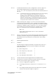
6.7.6.2 For REN determination the test configuration is shown in Figure 19.
The standard ring generator should generate at its terminals
75 V ±1 V a.c. r.m.s. at a frequency of 25 Hz ±0.5 Hz superimposed on
48 V d.c.
Note: A standard ring detector at ringing frequencies in the active ringing
state (i.e. with a ringing signal as described in Clause 5.5.1.1
applied) can be characterised as comprising a resistance of
4 kΩ ±5% in series with a 1 µF ±5% capacitor; this combination is
defined as having a REN of 1. The bridging impedance of the ring
detector at other than ringing frequencies would be expected to
comply with relevant Clauses of the Standard.
6.7.6.3 While monitoring the voltage V, the CE to be tested should be
connected to the terminals L+ and L–. Further CE having the same
nominal characteristics should be additionally connected in parallel
until the AC voltage V drops to below 40 V r.m.s. The total number
(n) of identical CE connected before the voltage drops to below
40 V r.m.s. should be used to calculate the REN as follows:
REN = 3/n
Where REN is determined to be 0.1 or less, it should be
deemed to be 0.1.
6.7.6.4 The DC component of the current flowing during application of ring
should be measured using the test configuration shown in Figure 7.
The milliammeter used should be a moving-coil DC responding
instrument.
6.7.7 Meter signal detection
6.7.7.1 General
The following input signal parameters may affect the output of a
meter signal detector and thus produce different meter signal
detector responses:
(a) RMS Voltage level V
(b) Pulse Frequency of the pulse F
(c) Pulse Duration t
1
(d) Pulse Repetition Interval time t
2
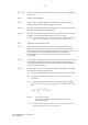
6.7.7.2 12 kHz transverse meter signal detector performance
6.7.7.2.1
The detector’s response should be tested for both the ‘Operate’
and the ‘Not Operate’ regions of Figure 8, using—
(a) the test configuration of Figure 20;
(b) the timing parameters of Clauses 5.5.1.3.1.3 and 5.5.1.3.1.4;
and
(c) the voltage and frequency limits bounded by the ‘Operate’
and the ‘Not Operate’ regions of Figure 8.