
Specifications
- 38 -
AS/CA S002:2010 COPYRIGHT
OCTOBER 2010
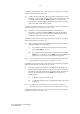
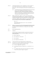
6.7.2 Return loss
The return loss, as defined in Annex B of ITU–T Rec. G.122 [15], should
be measured by a suitable bridge circuit or a vector impedance
meter as shown in Figure 13 using a test level as stated in Clause 6.5.
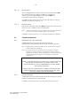
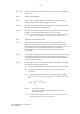
6.7.3 Impedance balance
Impedance balance is defined as the ratio U/V measured as shown
in Figure 14. The test should be carried out by injecting a signal of
3 V r.m.s. between the earth and the midpoint of two 300 Ω resistors
connected in series, in accordance with ITU–T Rec. O.9 [17]. Earth
should be either TRC or protective earth termination, or both.
Note: Impedance Balance = 20 log (U/V) dB.
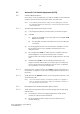
6.7.4 Insertion loss
Insertion loss should be measured as shown in the test circuit of
Figure 15.
Note: Insertion loss = 10 log (P1/P2), dB where P1 is the apparent power in
the load before the insertion of the CE (or a network), and P2 is the
apparent power that the same generator furnishes via the CE (or
network to the load).
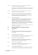
6.7.5 Noise performance
6.7.5.1
The following types of noise should be measured:
(a) Psophometric.
(b) Unweighted noise.
(c) Single frequency noise.
(d) Impulsive noise.
6.7.5.2 Depending on the type of noise, appropriate noise measurement
equipment should be used as shown in the test circuit of Figure 16,
Figure 17 or Figure 18.
Note 1: If the CE has an acoustic input device, the tests should be
performed with an ambient noise level of less than 30 dBA.
Note 2: Equipment suppliers should provide details of a method for placing
the CE in the ON-LINE condition with no signal being applied to line
for a period of not less than 10 min.
6.7.6 Ringer sensitivity, REN and DC component determination
6.7.6.1
For the ringer sensitivity test, the CE (one only) should be required to
respond to the signal specified in Clause 5.5.1.1.1.