
Specifications
- 37 -
AS/CA S002:2010 COPYRIGHT
OCTOBER 2010
6.2.4 Unless indicated elsewhere within this Standard for an individual test,
all component values in the test configuration should have a
tolerance of—
(a) ±1% for resistance;
(b) ±1% for capacitance; and
(c) –0%, +25% for inductors.
6.3 Fail-safe operation
Compliance with the requirements of fail-safe operation as specified
in Clause 5.1.1 may be checked by operation and inspection.
6.4 Emergency calling
Compliance with the emergency calling requirements as specified
in Clause 5.1.8 may be checked by operation and inspection.
6.5 Levels
6.5.1 Relative levels
The relative levels assigned to CE are +3 dBr transmit (into the PSTN),
–9 dBr receive (from the PSTN).
6.5.2 Send level
Unless otherwise specified, transmission tests should be carried out
with a send level of –10 dBm0 (i.e., –19 dBm at a –9 dBr point).
6.6 Test frequencies
Test frequencies should be in the range of 300 Hz to 4 kHz unless
otherwise specified in the relevant requirement clauses of this
Standard. Sufficient measurements should be carried out around all
nodal points of relevant masks, where applicable.
Note: Where the test frequencies are submultiples of a PCM sampling rate
of 8 kHz, an offset of 3 Hz to 20 Hz should be used to reduce errors in
level measurements.
6.7 Parameters to be tested
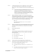
6.7.1 Impedance
6.7.1.1
The impedance presented by the CE (or network) should be
measured by a suitable bridge circuit or a vector impedance meter
as shown in Figure 13 using a test level as stated in Clause 6.5.
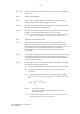
6.7.1.2 The series impedance of equipment intended to be connected
between CE in the OFF-LINE state and the PSTN should be tested
with a high impedance voltmeter in the configuration shown in
Figure 24.