
Specifications


- 30 -
AS/CA S002:2010 COPYRIGHT
OCTOBER 2010
(ii) For at least the latter half of the Break pulse time the
peak-to-peak amplitude of any oscillation shall not
exceed 12 V.
Compliance with Clause 5.5.1.8 should be checked by using the
methods relating to decadic signalling tests described in
Clause 6.7.11.
5.5.1.9 DTMF signalling
CE which generates DTMF signals is to comply with the following:
Note: The use of DTMF address signals is preferred as the standard method
of operation.
(a) Signalling frequencies
(i) The DTMF signals generated shall consist of pairs of
frequencies in accordance with ITU–T Rec. Q.23 [20] and
shall be allocated to the various digits, symbols and
characters as shown in Table 5.
(ii) The tolerance of each frequency generated shall be less
than ±1.5%.
Compliance with Clause 5.5.1.9(a) should be checked by using the
methods described in Clauses 6.7.8 and 6.7.9.
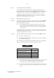
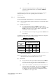
TABLE 5
DTMF signalling frequencies
Low Group
Frequencies
High Group Frequencies (Hz)
(Hz) 1209 1336 1477 1633
697 1 2 3 A
770 4 5 6 B
852 7 8 9 C
941 * 0 # D
Note 1: The provision of the frequency combinations shown as ‘A, B, C, D’ in
Table 5 is not mandatory.
Note 2: The designations ‘A, B, C, D’ should not be confused with the
alphanumeric allocations detailed in Clause 5.1.6.4.
(b) Send levels
(i) The power level of any fundamental frequency shall be
between –5 dBm and –22 dBm for line lengths between
0 km and 4.2 km using 0.40 mm conductor cable.
(ii) For DC line conditions, provided by DC feed resistances
between 400 Ω and 2300 Ω, the power level difference
between any two fundamental frequencies shall be
2 dB ±2 dB on a zero line length. The higher frequency
tone shall be at the higher level.