
Specifications


- 29 -
AS/CA S002:2010 COPYRIGHT
OCTOBER 2010
5.5.1.8 Decadic signalling
Decadic signalling functionality may not be implemented in all
carrier networks and access technologies. Therefore the
implementation of decadic signalling in CE is not recommended.
The use of DTMF address signalling is recommended.
For the purposes of this Clause, a Break pulse is defined as the DC
line condition with less than 2.8 mA of line current flowing and a
Make pulse is defined as the DC line condition with greater than
12 mA of line current flowing.
CE which generates decadic pulses is to comply with the following:
(a) Characteristics of pulses;
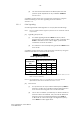
The following requirements apply for decadic loop-disconnect
pulses when the CE is connected in a resistive circuit of 1900 Ω
and a feed voltage of 48 V d.c. shown in Figure 11:
(i) ‘Break’ pulse shall be in the range 60 ms to 70 ms
inclusive.
(ii) ‘Make’ pulse shall be in the range 30 ms to 40 ms
inclusive.
(iii) Contact bounce shall not exceed 0.5 ms.
(b) Resistance during transmission;
During transmission of decadic pulses the steady state DC
resistance of the CE (when measured in a resistive circuit of
1900 Ω shown in Figure 11) shall be:
(i) For the Make period: within the requirements of
Clause 5.5.1.5.1.
(ii) For the Break period: greater than 100 kΩ with 100 V d.c.
applied.
(iii) For the Inter-digital Pause: within the requirements of
Clause 5.5.1.5.1.
(c) Interdigital pause timing;
The interdigital pause period separating consecutive decadic
pulse trains shall be within the range of 750 ms to 3 s unless due
to a programmed pause.
Note: A pause of 800 ms is recommended.
(d) Pulse voltage wave shape;
The voltage when measured in the test circuit shown in
Figure 12 shall comply with the following:
(i) The peak voltage measured across the terminals of the
CE shall be less than 230 V.