COMMUNICATIONS ALLIANCE LTD AUSTRALIAN STANDARD AS/CA S002:2010 Analogue interworking and non-interference requirements for Customer Equipment for connection to the Public Switched Telephone Network
Australian Standard – Analogue interworking and non-interference requirements for Customer Equipment for connection to the Public Switched Telephone Network This Standard is issued in draft form for public comment as DR AS/CA S002:2010.
-i- FOREWORD General This Standard was prepared by the CECRP/WC5 : General Standards for Customer Equipment Working Committee and most recently revised by the WC23 : PSTN Customer Equipment Revision Working Committee. It is one of a series of Telecommunication Standards developed under the Memorandum of Understanding between the Australian Communications Authority (ACA) and the Australian Communications Industry Forum.
- ii - Standards revision Australian Standards (AS/ACIF and AS/CA Standards) developed by the Communications Alliance are updated according to the needs of the industry, by amendments or revision. Users of these Standards should make sure that they possess the latest amendments or editions.
- iii - Introduction This introduction for the AS/ACIF S002:2010 Analogue interworking and noninterference requirements for Customer Equipment for connection to the Public Switched Telephone Network Standard is not an authoritative section of this Standard and is only provided as guidance for the user of the Standard to outline its objectives and the factors that have been taken into account in its development and to list the principal differences between the new and the previous edition.
- iv - (i) a clarification to Clause 5.5.1.8 has been added noting that the implementation of decadic signalling in CE is not recommended; and (j) the Multifrequency Code (MFC) signalling scheme and transmission criteria have been removed (the former Appendix A in the 2005 edition).
-v- TABLE OF CONTENTS 1 INTERPRETATIVE GUIDELINES 1 1.1 Categories of requirements 1 1.2 Compliance statements 1 1.3 1.4 Definitions, expressions and terms Notes 1 1 1.5 References 1 1.6 Units and symbols 2 2 3 SCOPE REFERENCES 3 4 4 ABBREVIATIONS AND DEFINITIONS 6 4.1 Abbreviations 6 4.2 Definitions 7 4.2.1 4.2.2 Automatic call transfer equipment Carrier 7 7 4.2.3 Carriage Service Provider 7 4.2.4 Compound CE 7 4.2.5 Customer Equipment 7 4.2.6 4.2.
- vi - 5 4.2.27 4.2.28 Telecommunications Reference Conductor (TRC) Telephone typewriter 9 9 4.2.29 Twist 9 4.2.30 Voice Frequency (VF) 9 REQUIREMENTS 10 5.1 10 5.2 5.3 5.4 General 5.1.1 Fail-safe operation 10 5.1.2 Line polarity 10 5.1.3 Transmitted voltages 11 5.1.4 5.1.5 Line-powered CE Line connection 11 11 5.1.6 Keypads and dials 12 5.1.7 Insulation resistance of ring-in/loop-out PSTN lines 13 5.1.8 Emergency services access 14 Classification of CE 15 5.2.
- vii - 5.7 5.8 6 Automatic Call Transfer Equipment (ACTE) 33 5.7.1 General Requirements 33 5.7.2 Recorded Voice Announcement (RVA) option 33 5.7.3 Multiple calling option 34 Technical conditions for recording of telephone conversations 34 5.8.1 General 34 5.8.2 Tone transmission while recording 34 5.8.3 Incorporation of interlocking circuitry 34 5.8.4 Continuity of tone generation 34 5.8.5 5.8.
- viii - APPENDICIES A PSTN SERVICE TONE CHARACTERISTICS 59 B CE FOR EXCLUSIVE USE WITH CSS 61 C AUTOMATIC STUTTER DIAL TONE DETECTION 62 D DISTINCTIVE RING 64 FIGURES FIGURE 1 FIGURE 2 FIGURE 3 FIGURE 4 FIGURE 5 FIGURE 6 FIGURE 7 FIGURE 8 FIGURE 9 FIGURE 10 FIGURE 11 FIGURE 12 FIGURE 13 FIGURE 14 FIGURE 15 FIGURE 16 FIGURE 17 FIGURE 18 FIGURE 19 FIGURE 20 FIGURE 21 FIGURE 22 FIGURE 23 FIGURE 24 FIGURE 25 FIGURE 26 FIGURE 27 FIGURE D1 28 Test circuit for seizure state Test circuit for hold sta
-1- 1 INTERPRETATIVE GUIDELINES 1.1 Categories of requirements This Standard contains mandatory requirements as well as provisions that are recommendatory only. Mandatory requirements are designated by the words ‘shall’ or ‘shall not’. Clauses referring to STS CE identify requirements that are mandatory only for Customer Equipment (CE) interfaced to a Standard Telephone Service (STS) as defined by the Telecommunications (Consumer Protection and Service Standards) Act 1999.
-2- (f) 1.6 In the event of a discrepancy between this Standard and a referenced or sub-referenced document, this Standard shall take precedence. Units and symbols In this Standard the International System (SI) of units and symbols is used in accordance with Australian Standard AS ISO 1000 [1].
-3- 2 SCOPE 2.1 This Standard specifies the technical requirements for CE and in the case of compound CE the parts of the compound CE that are designed or intended for connection to an analogue PSTN two-wire service. 2.2 This Standard does not apply to CE or the parts of compound CE that are designed or intended for connection to a DSL service operating over a shared metallic local loop with an analogue PSTN two-wire service. 2.
-4- 3 REFERENCES Publication Title Australian Standards [1] AS ISO 1000-1998 The international System of Unit (SI) and its application. [3] AS/NZS 3080:2003 Telecommunications installations Generic cabling for commercial premises (ISO/IEC 11801:2002, MOD) [3] AS/NZS 60950.
-5- Publication Title ITU–T and CCITT Recommendations [12] Annex to ITU Operational Bulletin Nr. 781 – 1.II.2003 Various tones used in national networks (According to ITU-T Recommendation E.180)(03/1998) [13] E.161 (02/2001) Arrangement of digits, letters and symbols on telephones and other devices that can be used for gaining access to a telephone network [14] E.164 (02/2005) The international public telecommunication numbering plan [15] G.
-6- 4 ABBREVIATIONS AND DEFINITIONS For the purposes of this Standard, the following abbreviations and definitions apply: 4.
-7- 4.2 Definitions 4.2.1 Automatic call transfer equipment Equipment associated with two or more exchange lines which, on detecting an incoming call on one exchange line, automatically originates a call, using another line, to a predetermined number. 4.2.2 Carrier Refer to the Telecommunications Act 1997. 4.2.3 Carriage Service Provider Refer to the Telecommunications Act 1997. 4.2.
-8- 4.2.10 Emergency call person Refer to the Telecommunications Act 1997. 4.2.11 Facility Refer to Section 374(2) of the Telecommunications Act 1997. 4.2.12 Fleeting test reversal A short duration (40 ms to 200 ms) reversal of line potential that may be applied at any time during outgoing call set-up. 4.2.
-9- 4.2.20 Ring-in/Loop-out PSTN line A both-way call set-up line connection with the PSTN. Incoming signalling to CE is by the application of a ring signal at the PSTN exchange. Outgoing signalling from CE is by the application of a DC loop at the CE. 4.2.21 Ringer Equivalence Number (REN) An approximate value of loading presented to the line during the ringing state, and based on the capacitance applied to the line when the CE is OFF-LINE. 4.2.
- 10 - 5 REQUIREMENTS 5.1 General 5.1.1 Fail-safe operation 5.1.1.1 CE shall not cause harm or damage to a Telecommunications Network or Facility if any of the following events occur: (a) Failure of any mechanical or electrical component in the CE. (b) Failure of any power supplies resulting in total or partial loss of power to the CE. (c) Discharge or partial discharge of any battery supply associated with the CE. (d) Incorrect manual operation of the CE. 5.1.1.
- 11 - 5.1.3 Transmitted voltages Voltages transmitted to a Telecommunications Network from CE, in any line condition, are not to exceed the limits for Telecommunications Network Voltages (TNV), as specified in AS/NZS 60950.1 [3]. Note: 5.1.4 AS/NZS 60950.1 [3] specifies applicable safety requirements of CE. Line-powered CE The current drawn by CE when connected to a source of— (a) 100 V d.c.; and (b) 50 V d.c. shall not exceed that which would be drawn by 1 MΩ resistor replacing the CE.
- 12 - b. Socket Type 611. c. Socket Type 612. d. Miniature 6-position socket as specified in ANSI/TIA 968 A 2002 [9]. e. Miniature 8-position socket as specified in ANSI/TIA 968 A 2002 [9]. The PSTN allocations for the various socket types are shown in Figure 3. Note 2: The miniature 8-position socket specified in ANSI/TIA 968 A 2002 [9] is also specified in IEC 60603 7 [11] Compliance with Clause 5.1.5 should be checked by inspection. 5.1.6 Keypads and dials 5.1.6.
- 13 - TABLE 2 Standard ten-pushbuttons keypad arrangement and numbering Note: 5.1.6.4 1 2 3 4 5 6 7 8 9 * 0 # The ‘*’ and ‘#’ symbols are commonly known as ‘star’ and ‘hash’ respectively.
- 14 - termination separately, if provided. Any internal protective devices shall remain connected for each test. 5.1.7.2 CE incorporating a message wait indicator that is intended for connection to a customer switching system are to comply with the requirements of Appendix B. 5.1.7.3 CSS are to comply with the requirements of AS/CA S003 [4]. 5.1.8 Emergency services access 5.1.8.
- 15 - Compliance with Clause 5.1.8 should be checked by using the method described in Clause 6.4. 5.1.8.5 Keypad Locks CE for voice communications incorporating a keypad lock for the purpose of minimizing accidental dialling of the emergency number 000 should be provided with clear instruction for the user, either via electronic display or labelling on the CE to unlock the keypad when required to make an emergency call. 5.2 Classification of CE 5.2.1 General 5.2.1.
- 16 - (b) If the CE provides local DC feed to the terminating STS CE, then the CE shall meet the requirements for Answer/Seizure/Hold signals and Idle/Release signals of Standard analogue telephone Local Port (On Premises and Off Premises) in AS/CA S003 [4].
- 17 - 5.2.4 Bridging equipment 5.2.4.1 Bridging equipment, including line termination equipment in the OFF-LINE state, is high impedance equipment connected in parallel with the line terminating equipment. It does not provide an ON-LINE termination. In general, it remains in the circuit irrespective of whether the line terminating equipment is in the ON-LINE or OFF-LINE condition.
- 18 - 5.3.3.2 The specifications of the intrusion tone alternatives at the PSTN interface port (+3 dBr relative level point) are— (a) an initial burst of 425 Hz ±10 Hz for 80 ms to 800 ms at a level in the range –7 dBm to –13 dBm, repeated at intervals of 15 s ±3 s; or (b) an initial burst of 425 Hz ±10 Hz for 800 ms ±10% at a level in the range –7 dBm to –13 dBm.
- 19 - (d) 5.3.4.2 Number Unobtainable (NU) Tone (i) Frequency 425 Hz ±10 Hz. (ii) Cadence 2.5 s on, 0.5 s off, ±10%. Pre-answer levels The level of audible supervisory tone (as specified in Clause 5.3.4.1) measured during the ‘on’ period of the cadence when terminated in a 600 Ω resistive impedance shall be in the range of –7 dBm to –13 dBm, with a zero line length. 5.3.4.
- 20 - Compliance with Clause 5.3.5.1 should be checked by operation and inspection. 5.3.5.2 Recognition of Telecommunications Network service tones CE which relies on the detection of specific pre-answer service tones for automatic operation shall operate normally on receipt of those service tones as transmitted from the Telecommunications Network over the range –9 dBm to –24 dBm and for nominal frequency and cadence as detailed in Appendix A.
- 21 - 2.5 s. The answering tone should be in the range from –7 dBm to –13 dBm; or (c) a post-answer tone dissimilar from a PSTN dial tone, PSTN ring tone, busy tone, or NU tone, as described in Appendix A. Compliance with Clause 5.3.5.3.2 should be checked by using the method described in Clause 6.7.9 as appropriate. 5.3.5.4 Commencement of dialling 5.3.5.4.1 CE which is not able to detect dial tone shall not commence dialling earlier than 2.
- 22 - 5.3.5.6 Calling message If a CE transmits a voice message after an automatically initiated call is answered, then that CE should include, in the voice message itself, a stored or synthesised message which identifies the calling party. Compliance with Clause 5.3.5.6 should be checked by operation and inspection. 5.3.5.
- 23 - 5.4.2.3 Voice frequency transmissions The one-minute mean power level of signals transmitted to line within the frequency range 300 Hz to 3.4 kHz except for DTMF signals, supervisory tones, speech and music shall not exceed –10 dBm. Compliance with Clause 5.4.2.3 should be checked by using the methods described in Clauses 6.7.9.1, 6.7.9.2, and 6.7.9.3 with R in Clause 6.7.9.2 and Figure 23 set to 600 Ω. 5.4.2.4 Signals greater than 3.4 kHz 5.4.2.4.
- 24 - Compliance with Clause 5.4.2.4.2 should be checked by using the methods described in Clauses 6.7.9.1, 6.7.9.2, and 6.7.9.5(b) with R in Clause 6.7.9.2 and Figure 23 set to 135 Ω. 5.4.3 Impedance 5.4.3.1 OFF-LINE state The impedance presented by the CE in the OFF-LINE state should be greater than 15 kΩ over the range 300 Hz to 3400 Hz. 5.4.3.
- 25 - (b) Single-frequency noise power Any single frequency (in particular the sampling frequency and its submultiples where appropriate) over the range 30 Hz to 20 kHz, measured selectively with a 30 Hz bandwidth, shall not exceed –47 dBm. (c) Impulsive noise The number of noise counts above a threshold level of –32 dBm shall not exceed five counts in 5 minutes, measured using an impulsive noise counter compliant with ITU-T Rec. O.71 [19], using the 600 Hz to 3 kHz filter described in § 3.5 therein.
- 26 - 5.5.1.1.2 CE should not recognise as a ring signal an AC voltage of less than 10 V r.m.s., or a ring signal of less than 100 ms duration. 5.5.1.1.3 CE in the OFF-LINE state should withstand 2 min of continuous noncadence, 90 V r.m.s. ring signal at 55 Hz superimposed on 48 V d.c. The ring signal should be applied to the terminals of the CE. 5.5.1.1.4 Under fault conditions, ring signal voltage may also be applied to the line terminals of the CE which is in the ON-LINE condition.
- 27 - 5.5.1.3.1.3 The meter signal detector should recognise meter signals in the range 100 ms to 380 ms inclusive, at a maximum repetition frequency of 1.25 Hz. 5.5.1.3.1.4 The meter signal detector should not respond to— 5.5.1.3.1.5 (a) meter signals less than 50 ms duration; (b) meter signals greater than 500 ms duration; and (c) signals occurring later than 800 ms after a release signal is initiated for an outgoing call.
- 28 - 5.5.1.5 Hold state 5.5.1.5.1 During the hold state, the DC characteristics of CE providing a line termination shall not be within the ‘Prohibited’ Region A of Figure 10. 5.5.1.5.2 Momentary breaks during hold state shall not exceed 2.5 ms. 5.5.1.5.3 CE designed to work in parallel with other CE should not have DC characteristics within the ‘Not Recommended’ Region B of Figure 10. Compliance with Clause 5.5.1.5 should be checked by using the method described in Clause 6.7.10. 5.5.1.5.
- 29 - 5.5.1.8 Decadic signalling Decadic signalling functionality may not be implemented in all carrier networks and access technologies. Therefore the implementation of decadic signalling in CE is not recommended. The use of DTMF address signalling is recommended. For the purposes of this Clause, a Break pulse is defined as the DC line condition with less than 2.8 mA of line current flowing and a Make pulse is defined as the DC line condition with greater than 12 mA of line current flowing.
- 30 - (ii) For at least the latter half of the Break pulse time the peak-to-peak amplitude of any oscillation shall not exceed 12 V. Compliance with Clause 5.5.1.8 should be checked by using the methods relating to decadic signalling tests described in Clause 6.7.11. 5.5.1.9 DTMF signalling CE which generates DTMF signals is to comply with the following: Note: (a) The use of DTMF address signals is preferred as the standard method of operation.
- 31 - Compliance with Clause 5.5.1.9(b) should be checked by using the method described in Clause 6.7.8. (c) Output rise and fall times The output rise and fall times of the envelope of each tone of each digit, measured between 10% and 90% of full amplitude, shall be within 5 ms with the CE connected to all line lengths between 0 km and 4.2 km using 0.40 mm cable terminated in 600 Ω. Compliance with Clause 5.5.1.9(c) should be checked by using the methods described in Clauses 6.7.8 and 6.7.9.
- 32 - 5.5.1.10 Recall signal The recall signal used to access enhanced network features, shall be a break in the loop holding condition for a duration of 100 ms ±20 ms. The characteristics of the break shall be in accordance with Clause 5.5.1.8(b)(ii). Compliance with Clause 5.5.1.10 should be checked by using the methods described in Clauses 6.7.11. 5.5.1.11 Release signal The release of a PSTN connection shall be indicated by the removal of the DC loop condition on the exchange line.
- 33 - 5.7 Automatic Call Transfer Equipment (ACTE) 5.7.1 General Requirements Some items of CE, including CSS, provide the facility to automatically transfer calls received from the PSTN, back onto the PSTN. Note: 5.7.1.1 In the following requirements, Party A is the calling party, Party B is the originally called party and Party C is the party that Party B wants calls forwarded to. The following requirements apply to ACTE: (a) A visual signal should be provided when a call is in progress.
- 34 - 5.7.2.2 The RVA should identify the Party B ACTE and should include a message similar to the following example: ‘The number you have called is unattended at present and your call is being directed to another number. Please wait for normal service tones.’ 5.7.2.3 The ACTE should commence dialling the Party C as soon as the transmission of the RVA is commenced. 5.7.2.
- 35 - much common circuitry as is practicable so as to ensure that under fault conditions the recording of a telephone conversation is unlikely to occur without the recording tone generator transmitting warning tones to line. 5.8.6 Distant party notification and recording tone CE should comply with the following: (a) Distant Party Notification Recording tone should be transmitted to the distant party during recording of a conversation.
- 36 - 6 TESTING 6.1 Verification of compliance with requirements Compliance with all mandatory requirements in this AS/ACIF Standard is to be verified. This may be done by direct measurement, modelling and analysis, operation or inspection. Methods for demonstrating compliance of CE with the requirements clauses specified in this Standard are described in Clauses 6.2 to 6.
- 37 - 6.2.4 6.3 Unless indicated elsewhere within this Standard for an individual test, all component values in the test configuration should have a tolerance of— (a) ±1% for resistance; (b) ±1% for capacitance; and (c) –0%, +25% for inductors. Fail-safe operation Compliance with the requirements of fail-safe operation as specified in Clause 5.1.1 may be checked by operation and inspection. 6.4 Emergency calling Compliance with the emergency calling requirements as specified in Clause 5.1.
- 38 - 6.7.2 Return loss The return loss, as defined in Annex B of ITU–T Rec. G.122 [15], should be measured by a suitable bridge circuit or a vector impedance meter as shown in Figure 13 using a test level as stated in Clause 6.5. 6.7.3 Impedance balance Impedance balance is defined as the ratio U/V measured as shown in Figure 14. The test should be carried out by injecting a signal of 3 V r.m.s.
- 39 - 6.7.6.2 For REN determination the test configuration is shown in Figure 19. The standard ring generator should generate at its terminals 75 V ±1 V a.c. r.m.s. at a frequency of 25 Hz ±0.5 Hz superimposed on 48 V d.c. Note: 6.7.6.3 A standard ring detector at ringing frequencies in the active ringing state (i.e. with a ringing signal as described in Clause 5.5.1.
- 40 - 6.7.7.2.2 Transverse impedance should be tested using the test configuration of Figure 13. 6.7.8 DTMF signal sending 6.7.8.1 DTMF levels and DTMF signal timing should be measured using a suitable waveform recorder and signal processor. 6.7.8.2 The main frequencies and levels should be measured using the test circuit shown in Figure 21 and Figure 22. 6.7.8.3 Distortion should be measured at the CE using the test circuit shown in Figure 21, but with the artificial line set to 0 km length.
- 41 - Note 2: In practice, when measuring sustained signals from modems or similar devices, it may be convenient to observe the indication of the square-law detector and then to calculate the one-minute mean value. 6.7.9.4 For determining the measurement of peak to peak voltages required by Clause 5.4.2.2 a storage oscilloscope with a minimum bandwidth of DC to 10 MHz should be used in place of the spectrum analyser in the test circuit shown in Figure 23. 6.7.9.
- 42 - 6.7.13 Service tone detection Performance of service tone detectors should be verified at levels of –9 dBm and –24 dBm using the test configuration of Figure 23 with the spectrum analyser and resistor ‘R’ replaced with a service tone generator to provide frequency and cadence of the applicable pre-answer tones as detailed in Appendix A. 6.7.14 Longitudinal power limits The CE under test should be connected to the measuring instrument as shown in Figure 27.
- 43 - FIGURE 1 Test circuit for seizure state FIGURE 2 Test circuit for hold state AS/CA S002:2010 COPYRIGHT OCTOBER 2010
- 44 - (a) 600 Series Single Line (b) 600 Series Two Lines (c) ANSI/TIA-968-A-2002 [9] SixPosition Modular Sockets connection for single or two lines (viewed from the front of socket) (d) ANSI/TIA-968-A-2002 [9] EightPosition Modular Socket connection for single or two lines (viewed from the front of socket) Note 1: The pair assignments align with AS/NZS 3080 [2]. Note 1: Note 2: The socket is not designed for insertion of a ANSI/TIA-968-A-2002 [9] FourPosition Modular Plug.
- 45 - FIGURE 4 Signal Power Levels limits above 3.
- 46 - FIGURE 6 Test circuit for ring voltage under fault conditions FIGURE 7 Test circuit for DC flowing during ring AS/CA S002:2010 COPYRIGHT OCTOBER 2010
- 47 - FIGURE 8 Operating range of 12 kHz meter signal detector AS/CA S002:2010 COPYRIGHT OCTOBER 2010
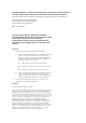
- 48 - Terminal voltage, V (V) 20 15 Prohibited Region A 10 5 (32, 9.6) (20,6) Not recommended Recommended (13.3, 4) 0 10 20 30 40 Line current, I (mA) FIGURE 9 Seizure state limits Terminal voltage, V (V) 20 15 Prohibited Region A 10 (20, 10) (15, 8.5) (9, 7.
- 49 - FIGURE 11 Decadic pulse test circuit FIGURE 12 Decadic pulse waveshape measurement AS/CA S002:2010 COPYRIGHT OCTOBER 2010
- 50 - FIGURE 13 Impedance or return loss measurement FIGURE 14 Impedance balance measurement AS/CA S002:2010 COPYRIGHT OCTOBER 2010
- 51 - FIGURE 15 Insertion loss measurement FIGURE 16 Noise measurement – psophometric and unweighted AS/CA S002:2010 COPYRIGHT OCTOBER 2010
- 52 - FIGURE 17 Single frequency noise measurement FIGURE 18 Impulsive noise measurement AS/CA S002:2010 COPYRIGHT OCTOBER 2010
- 53 - FIGURE 19 Test circuit for REN determination FIGURE 20 Test circuit – 12 kHz meter signal detection sensitivity AS/CA S002:2010 COPYRIGHT OCTOBER 2010
- 54 - FIGURE 21 Test circuit – DTMF level AS/CA S002:2010 COPYRIGHT OCTOBER 2010
- 55 - Component values for Figures 26(a), 26(b) and 26(c) Cable size (mm) R1 R2 R3 R4 R5 R6 (Ω) C1 (nF) C2 (nF) C3 (nF) (Ω) (Ω) (Ω) (Ω) (Ω) 0.40 56.1 112.2 35.6 71.3 11.1 22.3 38.0 24.0 7.5 0.64 37.5 75.0 22.5 45.0 4.5 8.9 63.0 38.0 7.
- 56 - FIGURE 23 Test circuit – tone level (other than DTMF) FIGURE 24 Test circuit – measurement of impedance for series equipment at ringing frequencies AS/CA S002:2010 COPYRIGHT OCTOBER 2010
- 57 - R Device Under Test 56 V (On-line state) R = 180 Ω ±5% Longitudinal Power Level (dBm) FIGURE 25 Test circuit – fault in hold state FIGURE 26 Longitudinal power level limits AS/CA S002:2010 COPYRIGHT OCTOBER 2010
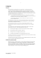
- 58 - (Note 7) FIGURE 27 Test circuit for measurement of longitudinal power level Note 1: If the equipment has separate protective and signal earth terminals they are connected together. Note 2: The two resistors R1 are to be matched to within 0.01%. Note 3: The measuring instrument is of high impedance, and capable of measuring over the frequency range 3.4 kHz to 30.175 MHz. Note 4: The measuring instrument is calibrated in dBm as if it was measuring across a resistive load.
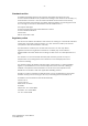
- 59 - APPENDIX A PSTN SERVICE TONE CHARACTERISTICS Tone Frequency Cadence Level (Hz) (s) (dBm) Max. Min Continuous (for a minimum of 10 s) –13 –24 0.1 ON, 0.04 OFF, repeated (for a minimum of 10 s) –13 –24 0.4 on, 0.2 off, 0.4 on, 2.0 off, repeated –13 –24 PRE-ANSWER Dial 425 or 425 * 25 or 400 + 425 + 450 400 + 425 Stutter Dial 425 * 25 or 400 + 425 + 450 Ringing 400 + 450 or 425 * 25 or 400 + 425 + 450 Busy 425 0.375 on, 0.375 off, repeated –13 –24 Congestion 425 0.
- 60 - Note 2: The receiving tolerances applicable to the tone parameters at the network boundary are as follows: (a) (b) Frequency tolerances: ± 20%; and Cadence tolerances: ± 20%; Note 3: The power levels of service tones at the network boundary vary in the range shown above. Note 4: This range of levels for Preanswer Tones relates to those originating in the Public Telecommunications Network.
- 61 - APPENDIX B CE FOR EXCLUSIVE USE WITH CSS B1 CE with message wait indicator Some CSS may use a higher voltage, applied from an extension port in the OFF-LINE state, as a signalling state. CE capable of detecting this signal should have the following: (a) An insulation resistance of not less than 30 kΩ, when tested with 100 V d.c. applied with either polarity. (b) Markings which clearly indicate that the CE may only be connected to the extension ports of a CSS.
- 62 - APPENDIX C AUTOMATIC STUTTER DIAL TONE DETECTION C1 General C.1.1 Line seizure for stutter dial tone detection CE may automatically seize the line to detect the presence or absence of stutter dial tone for the purposes of message wait indication. Where CE performs this function it shall do so in accordance with the requirements of this Appendix. C.1.
- 63 - C.2.3 Ability to initiate a call During an automatic stutter dial test, CE shall not prevent a customer who is attempting to initiate an outgoing call from receiving dial tone and being able to initiate that call. Note: C.2.4 When this condition is detected, stutter dial tone detecting CE is required to remove its DC loop so as to allow another CE to initiate a call attempt.
- 64 - APPENDIX D DISTINCTIVE RING D1 PSTN distinctive ring signal characteristics Distinctive Ring is a feature that provides the capability of associating a differing ring cadence with a particular type of incoming call. The Distinctive Ring is the mechanism used to indicate to the user that he/she is receiving a particular type of incoming call. Note: D2 The Distinctive Ring signals described in Appendix D are those provided by Telstra. Consult other carriers for possible variations.
- 65 - D.2.2 Prioritisation of Distinctive Rings Where the combination of call types that provide Distinctive Ring to the user would result in multiple simultaneous Distinctive Rings being provided, the Distinctive Ring for the type of call that has the highest priority (as indicated below) will be that which is actually delivered. D.2.3 List of priorities In the following list, Priority 1 is considered to be the highest, while Priority 7 is the lowest.
- 66 - TABLE D1 6 Distinctive ring applications Call Type Data Privacy Fax & Data Selective Ring Public SR 2 SR 1 SR 3 Centrex SR 2 SR 1 SR 3 Call Forwarding MSN Recall & Operator DR 0 DR 1 DR 2 DR 4 DR 5 DR 6 DR 7 X Public X Centrex X Public N1 N2 N3 Centrex N1 N2 N3 Public X Centrex X Internal Centrex and CUG Normal Calls Note: DR 3 X X Table E1 summarises the above information CUG Closed User Group MSN Multiple Subscriber Number N Number SR Selective Ring AS/CA
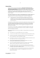
- 67 - D.2.4 Cadences Figure D1 shows the cadences for the eight ring patterns. All Ring and Silent Interval durations are in multiples of 200 ms. The cycle time for all cadences is 3 s. Note 1: The Distinctive Ring signals described in this diagram are those provided by Telstra. Consult other carriers for possible variations.
- 68 - PARTICIPANTS The Working Committee responsible for the revisions made to this Standard consisted of the following organisations: Organisation Membership Australian Communications and Media Authority Non-voting Comtest Laboratories Voting Cisco Systems Voting NEC Australia Non-voting Telstra Voting Thomson Telecom Australia Voting Trillium Communications Voting This Working Committee was chaired by Mike Johns of Communication Alliance, who also provided project management support.
Communications Alliance was formed in 2006 to provide a unified voice for the Australian communications industry and to lead it into the next generation of converging networks, technologies and services. In pursuing its goals, Communications Alliance offers a forum for the industry to make coherent and constructive contributions to policy development and debate.
Published by: COMMUNICATIONS ALLIANCE LTD Level 9 32 Walker Street North Sydney NSW 2060 Australia Correspondence PO Box 444 Milsons Point NSW 1565 T 61 2 9959 9111 F 61 2 9954 6136 TTY 61 2 9923 1911 E info@commsalliance.com.au www.commsalliance.com.au ABN 56 078 026 507 Care should be taken to ensure the material used is from the current version of the Standard or Industry Code and that it is updated whenever the Standard or Code is amended or revised.