
User Guide

Configuring PSpice Schematics
57
Snap-to-Pin
Snap-to-pin, when enabled, causes the endpoint of a wire
or bus segment to snap to the nearest pin if one is found
inside the radius defined by the Gravity setting.
Enabling or disabling snap-to-pin
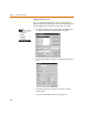
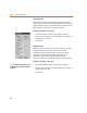
1 From the Options menu, select Display Options.
2 Select or clear the Snap-to-Pin check box to enable or
disable snap-to-pin.
3 Click OK.
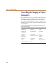
Grid Spacing
Grid Spacing defines the horizontal and vertical grid
spacing on your drawing area. The default spacing is 10
units. This corresponds to (and displays as) 0.10 inches for
US-standard page sizes, and 2.5 millimeters for metric
page sizes. The minimum grid spacing allowed is 0.01
inch, or .25 millimeters.
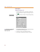
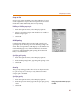
Specifying grid spacing
1 From the Options menu, select Display Options.
2 In the Grid Spacing frame, type the grid spacing value.
3 Click OK.
Gravity
The gravity setting specifies how close an object must be
to a pin to snap to it. Gravity is only functional when
snap-to-pin is enabled.
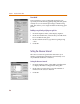
Specifying gravity
1 From the Options menu, select Display Options.
2 In the Snap-to-Pin frame, type the snap-to-pin gravity
value.
3 Click OK.
Gravity is on
l
y
f
unctiona
l
w
h
en snap-to-pin
is enabled.