
User Guide


Chapter 3 Using the Schematic Editor
30
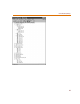
Symbols
Symbols are the graphical representation of parts, ports,
and other schematic elements. They are grouped by
functionality into symbol libraries. Each symbol contains
a specific set of attributes that define the symbol. You can
edit these attributes as well as create new attributes.
Symbols can share similar attributes and graphics.
Hierarchical symbols represent schematics and are the
mechanism that you use to create hierarchical designs.
Ports
Ports are symbols that form connecting points leading into
or out of the schematic page. Ports provide connectivity
between schematic pages and between levels of hierarchy.
They play an important role in determining names of
electrical nets.
Attributes
Parts, ports, wires (nets), buses, and most other symbols
have associated attributes. An attribute consists of a name
and an associated value. Attributes are used for Bill of
Materials reports, and simulation and layout netlists.
Annotations
Text, graphics, and annotation symbols are used to show
non-electrical information on the schematic, such as
comments and tables. Annotation symbols primarily
consist of text and graphics. Title blocks and page borders
are considered annotations. For more information on
adding annotations to your schematic, see Adding
Non-Electrical Information on page 4-126.
Ports are not p
h
ysica
l
connectors. I
f
you
w
ant a specific pin (such as a DB25 pin) you
must use a symbol for such a connector
from the “connect.slb” symbol library.
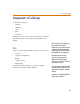
T
wo attri
b
utes o
f
a resistor are PKGTYPE
(package type) and VALUE.
Attribute
Name
Value
PKGTYPE = RC05
VALUE = 1K