
User Guide

Example—Drawing a Schematic
11
Drawing and Labeling Wires
Draw the wire labeled dataclk to connect pin 8 (CLK) on
U3 and pin 1 (A) on U8A.
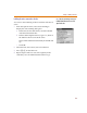
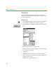
Drawing the dataclk wire
1 Click the Draw Wire button.
The pencil pointer indicates that you are ready to
draw a wire.
2 Click pin 8 of U3 to begin the wire.
3 Following the illustration in Figure 2, click where you
want each vertex of the wire. Each click ends a wire
segment and starts a new one.
4 Click pin 1 of U8A
Notice that the wire is now ended where you clicked
to place a pin. The pointer remains in the shape of a
pencil and you are ready to start another wire.
5 Wire the rest of the schematic to the bus, except for the
wires of the right sides of U5 and U6.
6 Right-click to stop drawing wires.
Labeling the dataclk wire
Label the wire connecting the CLK pin of U3 to the A pin
of U8A.
1 Double-click any segment of the wire to display the
Set Attribute Value dialog box.
2 Type
dataclk in the LABEL text box.
3 Click OK.