
User Guide


Chapter 10 Preparing Your Design for Board Layout
278
Using Connector Symbols that Represent the Entire
Connector
These symbols will have as many pins as the physical
connector they represent. You can wire signals directly to
the pins or connect labeled off-page (or global) ports to
each pin. The label indicates the signal name that will be
connected to the pin. Any off-page ports in the design
with that same signal name will be connected to that
connector pin.
Two connector symbols that represent an entire connector
are DB25F-B and EDGE4OM-B.
Using Connector Symbols that Represent One Pin of
a Connector
In cases where a connector has a large number of pins, you
may want to use a symbol that represents a single pin of
the connector so you can attach connector pins to nets
spread over multiple pages.
When an instance of such a connector symbol is placed on
the schematic, it is assigned an arbitrary reference
designator and gate. The reference designator indicates
which physical connector instance the connector pin is
part of (P1, for example), and the gate indicates which
physical pin (such as, 1 or 2). Therefore, the entire
connector is considered a multi-gate package with each
gate having a single pin. All connector pin instances with
the same reference designator are a part of the same
physical connector.
Usually, you would assign the reference designator and
gate manually. Otherwise, you could automatically
package the pins, however, this will result in an arbitrary
grouping of signals which is not usually desired. To
change the reference designator, double-click the
reference designator on the schematic. To change the pin
number (gate), double-click the pin number.
Two connector symbols that represent single pins of a
connector are DB25 and EDGE40.
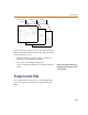
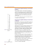
Figure 23 Entire Connector
Symbol
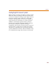
Figure 24 Single Pin Symbol