
User Guide


Connectors
277
Connectors
Connectors provide the interface between a PCB and the
rest of a system.
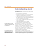
The distinction between connectors and ports on a
schematic is important and is shown in Table 14. Off-page
ports are not physical connectors, so you cannot use an
off-page port as a connector or a connector as an off-page
port. You may use them together if you want to have both
connectivity and a physical part by attaching an off-page
port to the pin of the connector.
Placing Connectors
Connectors are added by placing connector symbols on
the schematic. You can use the connector symbols shipped
with PSpice Schematics (found in the
connect.slb
symbol library) or you can create your own using the
symbol editor. (See Chapter 5,
Using the Symbol Editor.)
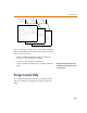
There are two styles of connector symbols:
• those representing the entire connector
• those representing a single pin of a connector
Table 14 Distinctions Between Connectors and Ports
Connectors Ports
define physical connection
points on the PCB
define logical connection
points on the schematic
are not included in layout
netlists
are included in layout
netlists
cannot be used to create
connectivity on the
schematic
are used to create
connectivity on the
schematic
During simu
l
ation, connectors are
l
arge
l
y
ignored except that you can attach a
marker to a connector pin to view
w
aveforms in Probe. You can also connect
stimuli to connector pins to simulate the
external interface to the circuit.