
User Guide


Example—Drawing a Schematic
9
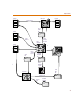
Placing resistors R1 and R2
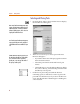
1 From the Draw menu, select Get New Part to display
the Part Browser dialog box (shown on 1-8
).
2 Type
R in the Part Name text box.
3 Click Place & Close.
The outline of the resistor becomes attached to the
pointer.
Note that as you move the pointer, the X and Y
coordinates at the left of the Status Bar (bottom of the
window) change. These coordinates show the location
of the pointer from origin 0,0 (upper left corner) to the
closest 0.01 inch (or closest mm if you are using a
metric page size).
4 Press C+R to rotate the resistor before placing it.
5 Move the pointer to the 2.40, 1.80 coordinates (within
a few hundredths of the inch is close enough) and click
to place the resistor on the schematic. If the
Stay-on-Grid option is enabled, parts are
automatically placed on the nearest grid point.
6 Move the pointer to 2.40, 3.90 and click again to place
the second resistor on the schematic.
7 Right-click to stop placing the part.
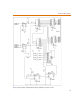
Placing resistors R3 through R6
You can quickly place resistors R3 through R6 using the
Auto-Repeat function.
1 From the Options menu, select Auto-Repeat to display
the Auto-Repeat dialog box.
a Set Horizontal Offset to 00.00 and Vertical Offset
to -00.20.
b Select the Enable Auto-Repeat check box.
c Click OK.
2 From the Get Recent Part list box on the toolbar, select
R.
As you p
l
ace parts, t
h
e numerica
l
portion o
f
the reference designator is automatically
assigned. For instance, if you place resistor
R2, the next resistor you place will be
designated R3.