
User Guide

Chapter 7 Creating and Editing Hierarchical Designs
244
Example—Creating a
Hierarchical Design
This example shows you how to create schematics from
the top level down. The design consists of a simple
schematic with a block representing a CMOS inverter and
a lower-level schematic for the inverter.
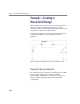
Follow this example to create the top-level circuit shown
in Figure 20 and the inverter schematic shown in
Figure 21.
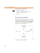
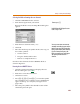
Figure 20 Top-level Schematic Drawing for CMOS Inverter
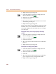
Drawing the Top-Level Schematic
To create the top-level schematic, start by placing a VSRC
power supply connected as an input to a block
representing a CMOS inverter. Draw the block, place a
resistor and two ground symbols, and connect the
components.