
User Guide

Chapter 6 Creating and Editing Symbols
222
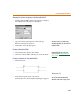
2 Click PART.
a Set its value to the name that you used in the
original definition box.
b Click Save Attr.
3 Click MODEL.
a Set its value to the same value as in your model or
subcircuit definition.
b Click Save Attr.
4 Click TEMPLATE.
The TEMPLATE attribute is the template for
generating the netlist entry for this device. The
TEMPLATE for this example looks like the following:
X^@REFDES %IN+ %IN- %OUT+ %OUT-
@MODEL
5 Click Save Attr.
6 Click OK.
7 Make any last changes and select Save from the File
menu.
You can now call up the diode bridge symbol for use
in a design.
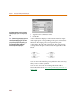
Parameter Description
X references a subcircuit definition
^@REFDES appends the hierarchical path (if there is
one) and the reference designator to the ‘X’
in the netlist
%
indicates that the item following will be a
pin name
@MODEL indicates the value of the MODEL attribute
will be placed here
MODEL an
d
TEMPLATE are on
l
y require
d
i
f
you are going to simulate.
Notice t
h
at t
h
e names use
d
matc
h
t
h
e pin
NAME as defined on the pins in the symbol;
the ORDER of the pins in the TEMPLATE are
listed in the same ORDER as those in the
subcircuit.
Looking at the symbol on page one, note
that IN+ is the same as node 1 in the
subcircuit definition.