
User Guide

Chapter 6 Creating and Editing Symbols
220
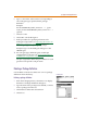
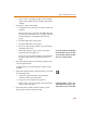
Placing Pins
To place pins
1 From the Graphics menu, select Place Pins.
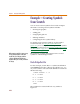
2 To place the pins:
a Place the IN+ and IN- pins as shown in Figure 19.
b Press C+ R to rotate the pin that is attached to
the cursor.
c Place the OUT+ and OUT- pins as shown in
Figure 19.
3 Double-click the default name (pin1 through pin 4) of
each pin to change their names to the following:
IN+
IN-
OUT+
OUT-
4 Single-click the names or numbers to move them to
their appropriate position.
Keep in mind that the ‘X’ on the pin is the point where
the wires will connect, and PSpice Schematics will
expect to find the connection points on the 00.10 grid
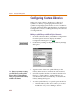
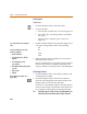
Finishing Touches
1 From the Options menu, select Display Options and
set the grid size to 00.01.
2 From the Graphics menu, select Draw Polyline to
draw the connecting lines between the diodes in the
bridge and also to the tail end of the pins.
If necessary, select Display Options from the Options
menu to turn off Stay-on-Grid. This will enable you to
move graphics without being restricted to the grid.
Note Do not move the pins. If they are not on 10-unit boundaries, you
will not be able to connect to them when in PSpice Schematics.
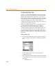
You can a
l
so c
l
ic
k
t
h
e pin to c
h
ange t
h
e
name.
T
o
d
isa
bl
e or mo
d
i
f
y t
h
e way t
h
e pin
numbers are displayed:
1 Double-click the pin.
2 In the Change Pin box, click Edit
Attributes.
3 In the Attributes box, select
pin=<number>.
4 Under What to Display, click the option
you want.
5 Click Save Attr.
6 Click OK.
T
his example has pin numbers set to
display ‘None’.