
User Guide


Example—Creating Symbols from Scratch
219
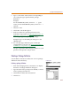
e Draw a line at a 45-degree angle across the right
angle of the symbol already created to denote the
cathode.
4 Place three copies of this diode:
a Drag the mouse to select the area that includes the
graphics.
Release the mouse to turn the lines red. If they do
not turn red, reselect the area, or S+ click the
unselected items to add them to the selected
group.
b From the Edit menu, select Copy.
c From the Edit menu, select Paste.
d Place one copy nearby; another copy will remain
attached to the cursor.
e Before placing the next two copies, rotate the
graphics by pressing C+ R.
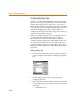
There are now four diode symbols: two pointing to
the upper right and two pointing to the lower
right.
5 From the Options menu, select Display Options and
reset the grid to 00.10.
Verify that Stay-on-Grid and Snap-to-Grid are still
enabled.
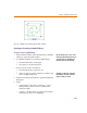
6 From the Graphics menu, select Draw Box to start the
box drawing mode:
a Click once (approximately) one grid square
southeast of the small origin box.
b Drag to the lower-right corner position.
c When you have the lower-right corner in position,
click to anchor it in place.
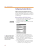
7 Select the diode symbols and move them to their
approximate locations inside of the box.
You can rotate grap
h
ics
b
y se
l
ecting Rotate
from the Edit menu. The cursor can still be
used to select menu commands, even when
in the process of placing a graphic.
I
f
you ma
k
e a mista
k
e, S+ c
l
ic
k
,
and hold the right mouse button, to select
and drag the box corner to a new location.