
User Guide


Chapter 6 Creating and Editing Symbols
218
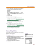
• The type of the part—the part type is most
commonly “component,” as it is in this example.
• An AKO or alias—use AKO if you want it to
inherit the graphics and attributes from another
symbol. Use Alias to assign additional names that
this symbol can be used for.
Drawing the Graphics
After the symbol has a definition, the next step is to draw
the graphics. For this example, it is possible to copy the
graphics from the regular diode symbol, however, that
particular graphic is oriented vertically and horizontally,
while this example calls for one that is at a 45-degree
angle.
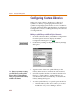
To draw the graphics
1 From the Options menu, select Display Options and
set the Grid Spacing to 00.02.
a If not already enabled, select Stay-on-Grid.
b If not already enabled, select Snap-to-Grid.
Enabling these features will assist in lining up the
segments of the symbol.
c Click OK.
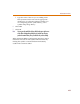
2 From the Graphics menu, select Draw Polyline to
change the cursor to a pencil.
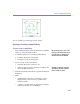
3 Draw the diode that is located in the upper right part
of the symbol:
a Click once to start drawing.
b Make a horizontal line 6 grid dots long. (Do not
count the starting grid dot.)
c Click once to anchor the end, move the cursor up 6
grid dots, and click to anchor the line midpoint.
d Continue drawing and close the triangle by
double-clicking at the starting point.
T
h
is examp
l
e
d
oes not use AKOs or a
l
iases.
Th
is pro
d
uces a
f
iner
d
rawing gri
d
,
approximately .02 inches between grid
dots.
I
t
d
oes not matter w
h
ere you
b
egin
drawing because it can be moved later.