
User Guide


Chapter 6 Creating and Editing Symbols
216
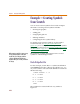
Example—Creating Symbols
from Scratch
You can create custom symbols from scratch in PSpice
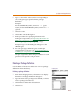
Schematics. Creating custom symbols includes:
• drawing the graphics
• adding pins
• changing the grid size
• defining attributes
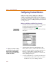
• configuring the new symbol library
To quickly create common symbols, use the Symbol
Creation Wizard (see Using the Symbol Wizard on
page 6-171), or for examples of creating common symbols
by copying existing ones (see Creating a Symbol by Copying
Another Symbol on page 6-173), or using AKOs (see Using
AKO Symbols on page 6-175).
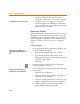
The following example demonstrates how to create a
symbol for a diode bridge rectifier.
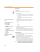
Diode Bridge Rectifier
For this example, assume there is a subcircuit definition
named BRIDGE stored in a library file called
mylib.lib
on your local drive. The subcircuit definition would look
like the following:
.SUBCKT BRIDGE1234
D1 4 1 D1N914
D2 1 3 D1N914
D3 4 2 D1N914
D4 2 3 D1N914
.ENDS
The symbol to be created will look very similar to
Figure 19.
W
h
en creating a sym
b
o
l
, it is not necessary
to have already defined a subcircuit or
model. The issue of having a model or
subcircuit definition will only become
important when you are ready to simulate
the design.