
User Guide

Chapter 6 Creating and Editing Symbols
196
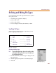
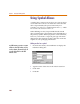
Bounding Box
The bounding box is the rectangular dotted line
surrounding the symbol. When you click a part from
within the schematic editor, the area in which you can
click and have that part be selected, is defined by the
bounding box of the symbol.
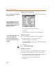
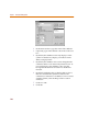
Resizing the bounding box
1 From the Graphics menu, select Bbox to change the
pointer to a pencil shape.
2 Click to begin sizing the bounding box.
3 Move the pointer down and to the right. A dotted box
outline follows the pointer.
4 Click at the location of the lower-right corner of the
bounding box.
• A
ll
pins must
b
e containe
d
wit
h
in t
h
e
bounding box for proper connections
to be made in the schematic editor.
• Hidden pins, like those found on digital
parts, do not have to be, and in most
cases are not, contained within the
bounding box.
• Attributes do not need to be contained
within the bounding box.