
User Guide

Chapter 6 Creating and Editing Symbols
194
Defining and Editing Hidden Power and Ground
Pins
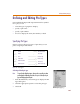
With the symbol editor, you can set a pin to be invisible. If
you set the visibility off, you must supply the name of a
connecting net (typically a global net like $G_DPWR or
$G_DGND) for the pin in the Net text box. The net is
recorded as a symbol attribute (not a pin attribute). The
IPIN(<pinname>)=<net name> attribute conveys the net
name.
If $G_<net names> are used for simulation reasons (this is
the case in the supplied Orcad libraries), they can be
mapped to a more conventional menu for printed circuit
board purposes through the .xnt files. For a specific
printed circuit board layout editor, there is a
<toolname>.xnt file that will convert a schematic net
name into a different one.
Note It is possible to map two distinct schematic net names into the same
PCB net name, shorting the two together.
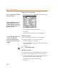
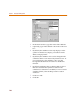
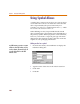
Defining a hidden pin
1 Double-click the pin to display the Change Pin dialog
box.
2 Select the Hidden check box.
3 In the Net text box, type the name of the net to which
the hidden pin is to be connected.
4 Click OK.
I
f
you set t
h
e visi
b
i
l
ity o
ff
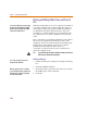
, you must supp
l
y
the name of a connecting net (typically a
global net like $G_DPWR or $G_DGND)
for the pin in the Net text box.
You can a
l
so se
l
ect t
h
e pin an
d
se
l
ect
Change from the Edit menu.
W
h
en you p
l
ace t
h
e part on a sc
h
ematic,
you can change the power or ground net to
w
hich the part is connected, by changing
the value of the attribute.