
User Guide


How to use this guide
17
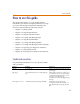
How to use this guide
This guide is designed so you can quickly find the
information you need to use PSpice Schematics. To help
you learn and use PSpice Schematics efficiently, this
manual is separated into the following sections:
• Chapter 1 - Getting started
• Chapter 2 - Using Design Manager
• Chapter 3 - Using the schematic editor
• Chapter 4 - Creating and editing designs
• Chapter 5 - Using the Symbol Editor
• Chapter 6 - Creating and editing Symbols
• Chapter 7 - Creating and editing hierarchical designs
• Chapter 8 - Preparing your design for simulation
• Chapter 9 - Using Design Journal
• Chapter 10 - Preparing your design for board layout
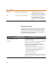
Symbols and conventions
Our printed documentation uses a few special symbols
and conventions.
Notation Examples Description
C+r Press C+r. Means to hold down the C key while
pressing r.
A, f, o From the File menu, choose Open (A, f,
o).
Means that you have two options. You
can use the mouse to choose the Open
command from the File menu, or you
can press each of the keys in
parentheses in order: first A, then f,
then o.
Monospace font
In the Part Name text box, type PARAM. Text that you type is shown in
monospace font. In the example, you
type the characters P, A, R, A, and
M.