
User Guide

Using Wires and Buses
111
Gravity
Gravity specifies how close an object must be to a pin to
snap to it. Gravity is only functional when snap-to-pin is
enabled.
Specifying gravity
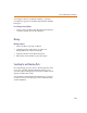
1 From the Options menu, select Display Options
(shown on page 4-110
).
2 In the Snap-to-Pin frame, in the Gravity box, type the
snap-to-pin gravity value.
3 Click OK.
Grid Spacing
Grid Spacing defines the horizontal and vertical grid
spacing on your drawing area. The default spacing is 10
units. This corresponds to 0.10 inches for US-standard
page sizes, and 2.5 millimeters for metric page sizes. The
minimum grid spacing allowed is 0.01 inch, or .25
millimeters.
Specifying grid spacing
1 From the Options menu, select Display Options.
2 In the Grid Spacing frame, type the grid spacing value
(shown on page 4-110).
3 Click OK.
Rubberbanding
Rubberbanding makes it easier to rearrange your
schematic for new parts and clean up the schematic when
necessary. You can move one or more selected objects to a
new location while maintaining connectivity.
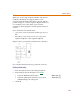
Results vary according to whether Orthogonal is enabled
or disabled. Figure 7 illustrates a rubberbanding move
with Orthogonal enabled, while Figure 8 shows the same
move with Orthogonal disabled.
Gravity is on
l
y
f
unctiona
l
w
h
en snap-to-pin
is enabled.