
User Guide

Chapter 4 Creating and Editing Designs
92
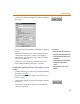
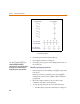
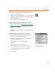
4 Select or type a value for any of the Display
Characteristics.
You can change any of the characteristics as described
in Table 9
.
5 Click OK to close the Change Attribute dialog box.
6 Click OK to close the Attribute Editing dialog box.
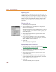
This procedure only changes the display characteristics
for the attributes of the one instance of this part on the
current schematic. To change display characteristics for
the attributes of a part for every instance placed on every
schematic, you have to change the global characteristics of
the symbol. See Editing the Default Attributes of a Symbol
on
page 4-94.
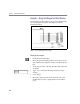
Table 9 Attribute Text Characteristics
Characteristic Explanation
Orient: Enables you to position the text
horizontally, vertically, upside down,
or down in relation to the defining
point of the text string.
Layer: Specifies a text display level as defined
by the Set Display Level function under
the Options menu. Defaults to Attribute
Text Layer. You can specify a
user-defined layer.
Size: Determines the size of the text of a
displayed text item. The size is
expressed as a percentage of the default
size (the default size is the font size for
the selected layer).
Hjust: Sets the horizontal justification for the
placement of text items (left, center, or
right).
Vjust: Sets the vertical justification for placing
text items (top, normal, or bottom).