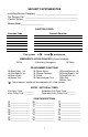
SECURITY SYSTEM NOTES Installing/Service Company _________________________________ For Service Call __________________________________________ Central Station ___________________________________________ Duress Code ____________________ FUNCTION CODES Function Code Controls Function This system is Y is not Y partitioned.
THIS MANUAL IS FURNISHED TO HELP YOU UNDERSTAND YOUR SECURITY SYSTEM AND BECOME PROFICIENT IN ITS OPERATION. ALL USERS OF YOUR SECURITY SYSTEM SHOULD READ AND FOLLOW THE INSTRUCTIONS AND PRECAUTIONS IN THIS BOOKLET. FAILURE TO DO SO COULD RESULT IN THE SECURITY SYSTEM NOT WORKING PROPERLY. THIS BOOKLET SHOULD BE KEPT IN AN ACCESSIBLE LOCATION FOR THE LIFE OF THE SECURITY SYSTEM. IF YOU DO NOT UNDERSTAND ANY PART OF THIS MANUAL YOU SHOULD NOTIFY YOUR INSTALLING COMPANY.
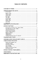
TABLE OF CONTENTS GLOSSARY OF TERMS .................................................................................... 4 UNDERSTANDING THE LIGHTS ...................................................................... 5 Armed Light.................................................................................................. 5 Bypass Light ................................................................................................ 5 Cancel Light .....................................................
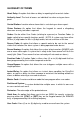
GLOSSARY OF TERMS Abort Delay: An option that allows a delay in reporting to the central station. Authority Level: The level of access an individual has when using an alarm panel. Central Station: Location where alarm data is sent during an alarm report. Chime Feature: An option that allows the keypad to sound a ding-dong whenever an entry/exit door is opened. Codes: Can be either User Codes (relating to a person) or Function Codes (a toggle switch to turn specific functions on/off).
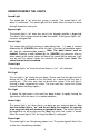
UNDERSTANDING THE LIGHTS Armed Light The armed light is “on” when the system is armed. The armed light is “off” when it is disarmed. The armed light will flash when there has been an alarm during the previous arm cycle. Bypass Light The bypass light is “on” when any zone in this keypad’s partition is bypassed. The zone(s) that is bypassed will also be illuminated. If the bypass light is “off”, no zones are bypassed. Cancel Light The cancel light will flash during an abort delay time.
Ready Light The ready light is “on” when the system is ready to arm and “flashes” if ready to force arm. The ready light is off when the system is not ready to arm because of a zone(s) being faulted. Stay Light The stay light is “on” when the all interior (motion detector) zones are bypassed. Zone Light The zone lights are “off” when everything is normal. A zone light will be “on” if the zone has been bypassed. If a zone light is “flashing”, that zone is in alarm or has been faulted.
KEYPAD FUNCTIONS ARMING YOUR SYSTEM IN THE “AWAY” MODE AWAY is used when the user is away from the premise and wants the interior protected. Listed below are the steps to arm in the AWAY Mode: tep 1 Close all protected doors and windows. • Ready light will be on or flashing when all protected zones and sensors are secure. NOTE: If any zones are bypassed, a sensor in that zone can be violated without affecting the ready light. • The security system will not arm if the ready light is not on or flashing.
Step 3 • Press the [STAY] key. • The stay light will illuminate indicating that all interior zones are bypassed. (All interior devices will bypass automatically, giving the user freedom of movement within the interior area.) • The bypass light will illuminate if any zone(s) are bypassed. If any zone(s) have been bypassed previously by the user, the light(s) corresponding to the bypassed zone(s) will illuminate, alerting the user that a zone(s) may be unprotected and can be faulted without an alarm.
CANCEL / ABORT FEATURE (Optional, see page 1) The cancel light will flash during an abort delay time. If a code is entered followed by the [CANCEL] key while this light is flashing, all abortable reports will stop the communication process. Entering a code followed by the [CANCEL] key during or after an alarm report to the central station will cause the cancel light to come on. It will stay on until the central station has received the cancel report.
CHANGING USER CODES Step 1 Your system must be in the Disarmed state to change user codes. Step 2 Press [7]-[5]. Step 3 Enter a “Master Arm/Disarm Code”. NOTE: For partitioned systems, someone changing the code of another person must have access to all or more partitions than the user being changed. Step 4 The ready light will flash. Step 5 Enter the 3-digit “user number”. You must always enter 3 digits, such as [0] - [0] - [3] for user 3, or [1] - [5] - [2] for user 152.
LIGHT 1 2 3 4 5 6 7 8 AUTHORITY LEVELS IF LIGHT 8 IS OFF Reserved (Note: Do not change if on.) Arm Only Arm Only After Closing Time Master Arm/Disarm (can program other codes) Arm/Disarm Bypass Zones Open / Close Reporting If this light is on, this code is programmed as a function code. Do not change! Press [#] - [#] to exit. Step 6 Press the [7] key. The ready light will flash. This moves you to the partition enable. (The user has access in partitions that are illuminated.
OTHER KEYPAD FUNCTIONS SETTING THE KEYPAD TONE Step 1 Press [7]-[0]. Keypad is now in the “Adjust Tone” mode. Step 2 Pressing the [1] key will make the keypad sounder go to higher tones, pressing the [2] key will make the keypad sounder go to lower tones. Step 3 When the desired tone is reached, press the [#] key to set this tone and exit from the “Adjust Tone” mode. CHANGE PARTITION – Optional Step 1 Press [7]-[1]. Step 2 Press a NUMBER key between 1 and 8 to change partitions momentarily.
RESET FUNCTION This function is used to reset Smoke Detectors, Zone Troubles, and Zone Tampers. Step 1 Disarm the system if not disarmed. Step 2 Press [7]-[7]. Resets have now been performed. Step 3 If the keypad begins beeping, the reset did not execute properly. Enter your code to silence the keypad. Wait a few minutes and repeat step 2 to attempt another reset. If the keypad still beeps after repeated attempts, please contact your installer. SET SYSTEM DATE Step 1 Press the [7]-[9]-[6].
Time Hour Code Time Hour Code Time Hour Code 12:00 Midnight 00 8:00 AM 08 4:00 PM 16 1:00 AM 01 9:00 AM 09 5:00 PM 17 2:00 AM 02 10:00 AM 10 6:00 PM 18 3:00 AM 03 11 7:00 PM 19 4:00 AM 04 11:00 AM 12:00 12 8:00 PM 20 5:00 AM 05 1:00 PM 13 9:00 PM 21 6:00 AM 06 2:00 PM 14 10:00 PM 22 7:00 AM 07 3:00 PM 15 11:00 PM 23 KEYPAD CONTROL TONES (BEEPS) A sounder is built into the keypad.
SERVICE MENU The service light will be “on” if the security system requires service. If the service light is “on”, press the [7] key followed by the [2] key to determine the service condition. One or more zone lights will illuminate indicating what service(s) is required. Call your service provider immediately for these problems. Below is a listing of what each light means in a service condition. LIGHT 1 PROBLEM SYSTEM FAULT - Press the [1] key.
EMERGENCY EVACUATION PLANS An emergency evacuation plan should be established for an actual fire alarm condition. For example, the following steps are recommended by the National Fire Protection Association and can be used as a guide in establishing an evacuation plan for your building. Draw up a floor plan of your home. Show windows, doors, stairs, and rooftops that can be used for escape. Indicate each occupant's escape routes. Always keep these routes free from obstruction.
SYSTEM NOTES 17
NX8-E USER’S MANUAL NX8EUA01 REV A (01-31-01)