Caddx® Installation Instructions Package This package includes instructions for the following Caddx products: ■ ■ ■ ■ ■ NetworX NX Series Receiver Modules—NX-408 & NX-408-I, NX-416 & NX-416-I, NX-448 & NX-448-I (Document Number 466-1427) NX-450 & NX-451 Door/Window Sensor (Document Number 466-1303-CDX) 60-686-43-EUR Door/Window Sensor (Document Number 466-1578) NX-470 & 60-659-43-EUR 4-Button Keychain Touchpad (Document Number 466-1478) NX-480 & 60-639-43-EUR Wireless Motion Sensor (Document Number 466-147
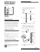
NetworX NX Series Receiver Modules NetworX NX Series Receiver Modules Document Number: 466-1427 Rev. E August 1998 1) After mounting the NX-8 cabinet, install the ground plane screws, washers, and nuts (included) in the holes on top of the cabinet (see Figure 1). TOP OF ENCLOSURE 9740G15A.DS4 60-732 Installation Instructions Product Summary The NX-Series Receiver Modules (8-zone NX-408, 16-zone NX-416, and 48-zone NX-448) add wireless capabilities to the Caddx® NetworX NX-8 control panel.
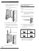
NetworX NX Series Receiver Modules 3) Install the module into the cabinet by turning the standoff sideways, then slide the module up onto the ground plane screw posts (see Figure 3). Wiring, Module Number DIP Switch Settings, and Power Up The following steps describe wiring the module to the NX8, setting the module number DIP switches, and powering up the NX-8. 1) Remove power (if applied) from the NX-8 control panel.
NetworX NX Series Receiver Modules 5) Apply power to the NX-8. The middle (red) LED on the module should start blinking. Table 2 describes the module’s status based on LED conditions. Table 2. Module Status Conditions LED Module Status Red-blinking Normal data communication with NX-8. Red-off No data communication with NX-8. Check wiring and power source. Green-blinking Receiving radio signals from Learn Mode wireless sensors. Green-off No radio signals currently being received.
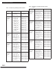
NetworX NX Series Receiver Modules Table 3. Module Programming Worksheet Table (cont.) Table 3. Module Programming Worksheet Table Location Location Segment 2 0 (Supervision) 1 - Normal ______hrs. (0 - 255 hours; default = 24 hours) Fire ______hrs. (0 - 255 hours; default = 4 hours) 1 (Zone 1) Assigned to module #_____.
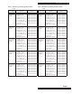
NetworX NX Series Receiver Modules Table 3. Module Programming Worksheet Table (cont.) Table 3. Module Programming Worksheet Table (cont.) Location Segment 1 Segment 2 Location Segment 1 Segment 2 10 (Zone 10) Assigned to module #_____.
NetworX NX Series Receiver Modules Table 3. Module Programming Worksheet Table (cont.) Page 6 Table 3. Module Programming Worksheet Table (cont.) Location Segment 1 Segment 2 Location Segment 1 Segment 2 20 (Zone 20) Assigned to module #_____.
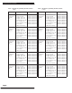
NetworX NX Series Receiver Modules Table 3. Module Programming Worksheet Table (cont.) Table 3. Module Programming Worksheet Table (cont.) Location Segment 1 Segment 2 Location Segment 1 Segment 2 30 (Zone 30) Assigned to module #_____.
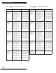
NetworX NX Series Receiver Modules Table 3. Module Programming Worksheet Table (cont.) Page 8 Table 3. Module Programming Worksheet Table (cont.) Location Segment 1 Segment 2 Location Segment 1 Segment 2 40 (Zone 40) Assigned to module #_____.
NetworX NX Series Receiver Modules trol panel is enrolling the module. After about 12 seconds, the service LED should turn off. Table 3. Module Programming Worksheet Table (cont.
NetworX NX Series Receiver Modules 5) 6) Enter [4] [9] [#] to enter the sensor learning location. The Ready LED should turn on and the Armed LED should turn off. Enter [XX] [✻], where [XX] is a zone number (1 through 48) and [✻] is the entry key. Note: Three beeps from the keypad indicates an entry error. This occurs if you enter a transmitter number that is not within the module’s zone block or if you try learning a sensor that is already learned into the module.
NetworX NX Series Receiver Modules 8) Press [✻] to save any changes. The panel is now waiting for the next location entry. Note: 9) Pressing [#] does not save changes to the current segment, but does save changes made in previous segments. Enter [EXIT] [EXIT] when all changes are completed. Programming Transmitter and Partition Settings 1) Enter [✻] [8] at the keypad. The five function lights should start flashing. 2) Enter the “Go To Program Code” (factory default is 9 7 1 3).
NetworX NX Series Receiver Modules 5) 6) Enter the tripped transmitters’ location. Observe keypad light 7 which should be on, indicating the transmitters’ signal is good. If keypad light 7 is off (transmitter test below margin), exit program mode and repeat steps 1-6 above. Troubleshooting Any transmitters that consistently test below margin should be rotated in mounting position (90°, 180°, or 270°) and retested.
NX-450, NX-451 Door/ Window Sensors NX-450, NX-451 Door/Window Sensors Document Number: 466-1303-CDX Rev. B September 1997 ■ If possible, locate sensors within 100 feet of the panel. While a transmitter may have a range of 500 feet or more out in the open, the environment at the installation site can have a significant effect on transmitter range. Sometimes a change in sensor location can help overcome adverse wireless conditions.
NX-450, NX-451 Door/Window Sensors Programming MOUNTING HOLES For complete programming instructions, refer to the NX-Series Receiver Modules Installation Instructions. Testing Door/Window Sensors 8888G01A.DS4 Figure 3. Mounting Hole Locations (Bottom View) 4. 5. 6. Remove the magnet from its base. Line up the arrow on the magnet with the mark on the sensor. Mount the magnet base no more than 3/8-inch away from the sensor base. Replace the magnet cover.
NX-450, NX-451 Door/Window Sensors To replace a sensor: 1. 2. 3. Test a known good sensor at the same location. If the system does not respond, avoid mounting a sensor at that location. If the replacement sensor functions, return the problem sensor for repair or replacement. Specifications ■ Power source: 2 AAA Alkaline batteries ■ Dimensions: L = 4.5” X W = 1.2” H = .
NX-450, NX-451 Door/Window Sensors Caddx Controls, Inc. 1420 North Main Street Gladewater, Texas 75647 Toll Free: 1-800-727-2339 FAX: (903) 845-6811 Caddx is a registered trademark of Caddx Controls, Inc.
Door/Window Sensor Door/Window Sensor Document Number: 466-1578 Rev. B May 1998 ■ ■ ■ Door/Window Sensor Spacers White: Part #60-189 8867g01a.ds4 60-686-43-EUR Magnet Spacers White: Part #60-188 INSTALLATION INSTRUCTIONS ■ Product Summary ■ The Door/Window Sensor can be installed on doors, windows, or virtually anything that opens and closes. During normal operation, the sensors transmit open (TRIP) and close (RESTORE) signals to the panel.
Door/Window Sensor ALIGNMENT MARKS SENSOR END VIEW SENSOR SIDE VIEW ALIGNMENT MARK ALIGNMENT MARKS MAGNET 8867G03A.DS4 Figure 1. Alignment marks 2) Remove the sensor cover by squeezing the cover ends firmly to release the tab on the cover from the slot on the sensor base. 3) Remove the circuit board from the sensor base by pulling back the plastic tab and lifting the battery to release the circuit board.
Door/Window Sensor Installation Guidelines Troubleshooting ■ Use the following guidelines if the system does not respond correctly when the sensor is activated. ■ Check programming and re-program sensor into panel if necessary. ■ Use an RF Sniffer (NX-468) test tool to verify that the sensor is transmitting. Constant beeps from the RF Sniffer indicate a runaway (faulty) sensor. Replace the sensor. ■ Change the position of or move the sensor to another location and test for correct response.
Door/Window Sensor Specifications Frequency: 433 MHz. Operating Temperature Range: 10 ° to 120 ° F. Compatibility: NX-408-I, NX-416-I, and NX-448-I Power Source: 3.6-volt lithium battery Transmit Range: At least 500 feet, open air Dimensions: L = 3.25” x W = 1.55” x W = 1.0” FCC Notice This device complies with FCC Rules Part 15. Operation is subject to the following two conditions: This device may not cause harmful interference.
NX-470 KeyChain Touchpad Document Number: 466-1478 Rev. E May 1998 NX-470 Keychain Touchpad ■ Light Button - arms system to STAY/INSTANT. ■ Star Button - performs EXIT button function. ■ Light and Star Buttons - when pressed simultaneously, activates a medical alarm. Specifications Power source: 12 V, 33 mAh alkaline battery Frequency: 319.5 MHz. (NX-470) 433 MHz. (60-659-43-EUR) Dimensions: L = 2.30” x W = 1.45” x H =.
NX-470 Keychain Caddx Controls, Inc. 1420 North Main Street Gladewater, Texas 75647 Toll Free: 1-800-727-2339 FAX: (903) 845-6811 Caddx is a registered trademark of Caddx Controls, Inc.
NX-480 Wireless Motion Sensor NX-480 Wireless Motion Sensor Document Number: 466-1479 Rev. D May 1998 Installation Guidelines Motion sensors are ideal whenever it is not practical to install Door/Window sensors on every opening. Large areas in an open floor plan, downstairs family rooms, and hallways are candidates for motion sensors. Motion sensors are not suitable for rooms where pets can enter. 60-639 Installation Instructions Use the following guidelines for installing motion sensors.
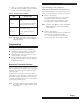
NX-480 Wireless Motion Sensor 0m 20 ft TOP VIEW 11 m 6m 10 ft 3m 0 ft 0m 20 ft 3m Person walking across detection path 8362G04B.DS4 Figure 1. Overhead (Bird’s Eye View) Detection Path ■ For best coverage, mount the sensor from 5 to 8 feet high in the corner of the area you want to protect. See the Animal Alley lens guidelines for mounting the Animal Alley lens.
NX-480 Wireless Motion Sensor Mounting the Sensor The sensor can be flush-mounted, incline-mounted, or corner-mounted depending on the application (see Figure 4). FLUSH MOUNT USE WITH ANIMAL ALLEY LENS INCLINED MOUNT WALL TAMPER KNOCKOUT USE WITH STANDARD LENS CORNER MOUNT 8362G01B.DS4 Figure 5. PIR Mounting Plate Knockouts 4. 8362G03A.DS4 5. Figure 4. Wall Mount Options: use the inclined position for surface or corner mounting with the standard lens.
NX-480 Wireless Motion Sensor 1. Locate the sensitivity pins by first removing the mounting plate and the sensor cover as described in steps 1 and 2 of Lens Replacement process. Note: When the walk test mode has ended, an alarm can be transmitted only after 3 minutes have passed since the previous alarm. This 3 minute lockout time reduces unnecessary RF transmissions in high traffic areas thereby extending battery life.
NX-480 Wireless Motion Sensor To relocate a sensor: 1. PIR COVER 2. 3. 4. PWB COVER Test the sensor a few inches from the original position. Increase the distance from the original position and retest until an acceptable location is found. Mount the sensor in the new location. If no location is acceptable, replace the sensor. To replace a sensor: LENS TABS 1. 2. 3. SENSOR BODY TAMPER SWITCH MOUNTING PLATE Test a known good sensor at the same location.
NX-480 Wireless Motion Sensor Caddx Controls, Inc. 1420 North Main Street Gladewater, Texas 75647 Toll Free: 1-800-727-2339 FAX: (903) 845-6811 Caddx is a registered trademark of Caddx Controls, Inc.