NX-8E Control Panel Installation Manual P/N I-NX8E-IM • REV C • ISS NOV12
Copyright © 2012 UTC Fire & Security Americas Corporation, Inc. Interlogix is part of UTC Climate Controls & Security, a unit of United Technologies Corporation. All rights reserved. This document may not be copied in w hole or in part or otherw ise reproduced without prior w ritten consent from UTC Fire & Security except w here specifically permitted under US and international copyright law . Disclaim er The information in this document is subject to change w ithout notice.
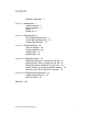
Content Important information ii Chapter 1 Introduction 1 Product overview 2 Board installation 3 Wiring 3 Module list 6 Chapter 2 Programming 9 LED keypad programming 11 Control panel programming 14 Programming locations 18 Chapter 3 Troubleshooting 59 General diagnosis 60 Trouble conditions 60 Voltage tables 63 Specifications 64 Appendix A Reporting codes 65 Reporting fixed codes in Contact ID and SIA 66 Reporting zone codes in Contact ID and SIA 68 Reporting Ademco Contact ID transmissions 69 Device numb
Important information This is the NX-8E Control Panel Installation Manual. This document includes an overview of the product and detailed instructions explaining how to install the NX8E board inside the enclosure and how to program the control panel. To use this document effectively, you should have the following minimum qualifications: • • ii A basic knowledge of electrical wiring and low-voltage electrical connections A basic knowledge of control panels.
Chapter 1 Introduction Summary This chapter provides an overview of your NX-8E Control Panel, including basic installation and terminal connections.
Chapter 1: Reporting codes Product overview The NX-8E Control Panel is a residential security and alarm system and provides the following features: • Sophisticated software allowing up to 240 users to interface with up to 192 zones and eight partitions. • Integrated fire and input/output modules. • Fast SIA and Contact ID formats. • System expansion with up to 32 modules. Keypads can include NX-148E-RF keypads that have built-in wireless receivers.
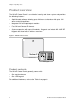
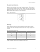
Chapter 1: Reporting codes Board installation Inside the metal enclosure, there are slots for board insertions. These allow the PC board to be positioned vertically (Figure 2 below). When you slide the board between the grooves of the slots, make sure the terminal strip is toward the front opening (toward you) to allow for the wire connections. Figure 2: Board installation Wiring Table 1 below lists wire lengths for one keypad at the end of the wire.
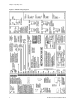
Chapter 1: Reporting codes Figure 3: NX-8E wiring diagram 4 NX-8E Control Panel Installation Manual
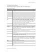
Chapter 1: Reporting codes Terminal descriptions Table 2 below describes the terminals shown in the wiring diagram. Table 2: NX-8E terminals Terminal Description R1 House telephone ring (gray). R Telephone ring (red) T Telephone tip (green) T1 House telephone tip (brown) EARTH Earth ground. Connect to a cold water pipe or a 6 to 10 ft. driven rod. AC AC input. Connect to a 16.5 V 40 or 50 VA Class II UL approved transformer.
Chapter 1: Reporting codes Terminal Description RELAY2 C = Closed dry contact rated 1 amp at 30 volts. NO = Normally open dry contact rated 1 amp at 30 volts. Note: These terminals can be set for 12 VDC. Install J12 for AUX1 and J13 for AUX2. COM Common used to ground any devices connected to relays RELAY1 NC = Normally closed dry contract rated 1 amp at 30 volts. C = Closed dry contact rated 1 amp at 30 volts. Note: These terminals can be set for 12 VDC. Install J12 for AUX1 and J13 for AUX2.
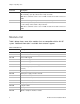
Chapter 1: Reporting codes Part number Description NX-548E 48-zone wireless receiver. NX-591E-GSM Cell interface. NX-870E Fire supervison module NX-1192E 192-zone LCD keypad. NX-1208E 8-zone LED keypad. NX-1248E 48-zone LCD keypad. NX-1308E 8-zone LED door design keypad. NX-1316E 16-zone LED door design keypad. NX-1324E 24-zone LED door design keypad. NX-1448E 48-zone fixed language icon keypad. Note: The maximum number of zones available is 192 regardless of the devices added.
Chapter 2 Programming Summary This chapter provides basic programming instructions and a description of the programming locations.
Chapter 2: Reporting codes Location 44 - Duress code 37 Locations 45 to 50 - Auxiliary outputs programming 37 Location 51 - Autotest control 40 Locations 52 to 55 - Times and days 41 Locations 56 to 83 - 4+2 format communicator codes 42 Location 84 - Daylight saving time 44 Locations 88 to 109 - Partition account codes and features.
Chapter 2: Reporting codes LED keypad programming This section describes how to program the address of each LED keypad, as well as the options that are available. The keypad must be addressed for control panel supervision of that keypad. Programming defaults include: • • • • Four-digit master code: 1, 2, 3, 4. Six-digit master code: 1, 2, 3, 4, 5, 6. Four-digit go to program code: 9, 7, 1, 3. Six-digit go to program code: 9, 7, 1, 3, 0, 0. To assign the keypad’s LEDs to start at a zone other than one: 1.
Chapter 2: Reporting codes LED 8 Keypad feature enabled Enable multiple partition viewing. Enable temporary viewing of all partitions by pressing *, 1, partition number. Keypad number and partition To set the keypad number and partition: 1. Enter *, 9, 4, program code. The Service LED and the Instant LED will flash. 2. Enter the keypad number (1 to 8). 3. Press *. The Instant LED will illuminate steady and the Service LED will remain flashing. 4. Enter the partition number (1 to 8) for the keypad.
Chapter 2: Reporting codes System clock To set the system clock: 1. Enter *, 9, 7, master code. The Service LED begins flashing. 2. Enter the clock time (military time). Hour: 00 through 23, where 00 is midnight, 01 is 1:00 a.m., 23 is 11:00 p.m. Minutes: 00 to 59. For example, 3.25 a.m. = 0, 3, 2, 5; and 5:00 p.m. = 1, 7, 0, 0. User codes To change the user codes: 1. Enter *, 5, master code. The Ready LED begins flashing. 2. Enter the two-digit user number (for example, 03 for user 3).
Chapter 2: Reporting codes assigned authority levels to all user numbers, or you can press # to exit assigning authority level programming.
Chapter 2: Reporting codes To enter program mode: 1. Press *, 8. The five function LEDs (Stay, Chime, Exit, Bypass, and Cancel) begin flashing. 2. Enter the go to program code (default 9, 7, 1, 3). If the go to program code entry is valid, the Service LED flashes, and the five function LEDs illuminate. You are now in program mode and can select the module to program.
Chapter 2: Reporting codes You are now ready to enter another programming location. If you attempt to program and invalid entry for a particular segment, the keypad beeps three times indicating an error and remains in that segment awaiting a valid entry. To exit program mode: 1. When you have completed all programming, press Exit to leave the selected module. 2. If there is another module to be programmed, select it by entering its address, followed by #.
Chapter 2: Reporting codes Feature selection data Feature selection data displays the current condition (on or off) for eight features associated with the programming location and segment selected. Pressing a button on the touchpad (1 to 8) that corresponds to the feature number within a segment toggles (on/off) that feature. You can select numerous features within one segment. To enter feature selection data: 1. Press a numeric key from 1 to 8 to select the feature.
Chapter 2: Reporting codes Programming locations This section describes all the programming options for the control panel. Quick start programming For most routine installations, the quick start locations allow you to enable a majority of the options available with the NX-8E (when communicating in Contact ID or SIA formats).
Chapter 2: Reporting codes Caution: A call-waiting cancel on a non call-waiting line prevents successful connection to the central station. Location 1 Phone 1 account code Location 1 has six segments of numerical data. Use this location to program the account code sent when phone 1 is dialed. The default for each segment is 10. Program a 10 in the segment immediately after the last digit of the account code. If the account code is six digits long, program all six segments.
Chapter 2: Reporting codes Data Format Description 11 4+2 express Two-digit event code DTMF transmission. 12 4+2 fast Two-digit event code 1900 Hz transmit 1400 Hz handshake double round parity 20 pps. 13 Ademco contact ID DTMF (see “Reporting Ademco Contact ID transmissions” on page 69. 14 SIA Frequency shift keys (see “Reporting fixed codes in Contact ID and SIA” on page 66). 15 Custom format See “Location 18 - Custom communicator format” on page 25.
Chapter 2: Reporting codes Segment 1 1. 2. 3. 4. 5. 6. 7. 8. Alarms and alarm restores. Opening and closings. Zone bypass and bypass restore. Zone trouble and trouble restores. Power fail, low battery, power restore, and low battery restore. Bell cut, telephone line cut, bell cut restore, telephone line restore. Test reports. Start and end programming, download complete. Segment 2 1. 2. 3. 4. 5. 6. 7. 8. Zone and box tamper and tamper restore. Auxiliary power overcurrent, ground fault, and restore both.
Chapter 2: Reporting codes Location 8 - Phone 2 communicator format Location 8 has one segment of numerical data. Use this location to program the communicator format used to transmit to the receiver connected to phone 2. Refer to your central station receiver documentation to determine which format is compatible. Table 6 on page 19 describes the formats for this location. If you need a format other than those listed, review the override options described in Location 18.
Chapter 2: Reporting codes Segment 1 1. 2. 3. 4. 5. 6. 7. 8. Alarms and alarm restores. Opening and closings. Zone bypass and bypass restore. Zone trouble and trouble restores. Power fail, low battery, power restore, and low battery restore. Bell cut, telephone line cut, bell cut restore, telephone line restore. Test reports. Start and end programming, download complete. Segment 2 1. 2. 3. 4. 5. 6. 7. 8. Zone and box tamper and tamper restore. Auxiliary power overcurrent and restore.
Chapter 2: Reporting codes Location 14 - Phone 3 communicator format Location 14 has one segment of numerical data. Use this location to program the communicator format used to transmit to the receiver connected to phone 3. Refer to your central station receiver documentation to determine which format is compatible. Table 6 on page 19 describes the formats for this location. If you need a format other than those listed, review the override options described in Location 18.
Chapter 2: Reporting codes Segment 1 1. 2. 3. 4. 5. 6. 7. 8. Alarms and alarm restores. Opening and closings. Zone bypass and bypass restore. Zone trouble and trouble restores. Power fail, low battery, power restore, and low battery restore. Bell cut, telephone line cut, bell cut restore, telephone line restore. Test reports. Start/end programming, download complete. Segment 2 1. 2. 3. 4. 5. 6. 7. 8. Zone and box tamper and tamper restore. Auxiliary power overcurrent and restore.
Chapter 2: Reporting codes Segment 1 1. 2. 3. 4. 5. 6. 7. 8. On for 1800 Hz transmit; off for 1900 Hz. On for 2300 Hz handshake; off for 1400 Hz. On for cksum parity; off for double round parity. On for two-digit event code; off for one-digit event code. Reserved. Reserved. On for 20 pps; off for 10 to 40 pps. On for 10 pps: off for 20 or 40 pps. Segment 2 1. 2. 3. 4. 5. 6. 7. 8. On for pager format (no handshake required). On for 1400/2300 handshake. Reserved. Reserved. On for contact ID. On for SIA.
Chapter 2: Reporting codes Segment 1 1. On enables two call answering machine defeat. 2. On enables tone sniff answering machine defeat. 3. On requires call back before download session. 4. Shutdown. (Can only be activated with the download software). 5. On locks all local programming. (Can only be activated with the download software.) 6. On locks programming of all locations associated with the communicator. (Can only be activated with the download software.) 7. On locks out download session.
Chapter 2: Reporting codes Locations 23 and 24 - Partition features Location 23 - Feature report selection/partition feature selection Location 23 has five segments of feature selection data. Use this location to enable certain features that are accessed or visible to the user from the system keypad. In addition, you can enable certain communicator reports in this location. Segment 1 1. 2. 3. 4. 5. 6. 7. 8. On enables quick arm. On enables re-exit. On enables automatic bypass.
Chapter 2: Reporting codes Location 24 - Entry/exit times Location 24 has six segments of numerical data. Use this location to program the entry/exit times (there are two separate entry/exit times). Segment 1 - Entry time 1. Entry time used when a delay 1 zone type initiates an entry delay. Default is 30, valid entries 30 to 255 seconds. Segment 2 - Exit time 1. Exit time used for all zones designated as delay 1. Default is 60, valid entries 45 to 255 seconds. Segment 3 - Entry time 2.
Chapter 2: Reporting codes Zone type Description 6. Instant Creates an instant alarm whenever it is tripped and the armed LED is on. 7. 24-hour silent Creates an instant silent alarm regardless of the armed state of the control panel. It does not display on the keypad. 8. Fire Illuminates the Fire LED and sounds the temporal siren each time the zone is shorted. The Fire LED flashes rapidly indicating a problem if the zone is open. 9. Entry/exit delay 2 A trip starts entry delay 2.
Chapter 2: Reporting codes Zone type Description 21. Gas detection Creates an instant alarm regardless of the armed state of the control panel. It displays on the keypad and activates the keypad sounder. 22. Low temperature detection Creates an instant silent alarm regardless of the armed state of the control panel. It displays on the keypad and activates the keypad sounder. 23. High temperature detection Creates an instant silent alarm regardless of the armed state of the control panel.
Chapter 2: Reporting codes Location 25 Zones 1 to 8 zone type Location 25 has eight segments of numerical data. Use this location to program the zone type for zones 1 to 8. Use segment 1 for zone 1, segment 2 for zone 2, etc. The segment defaults are 3, 5, 6, 6, 6, 6, 6, 6. Location 26 Zones 1 to 8 partition Location 26 has eight segments of feature selection data. Use this location to select the partitions (1 to 8) that zones 1 to 8 reside in.
Chapter 2: Reporting codes Location 35 Zones 41 to 48 zone types Location 35 has eight segments of numerical data. Use this location to program the zone type for zones 41 to 48. Use segment 1 for zone 41, segment 2 for zone 42, etc. The segment defaults are 6, 6, 6, 6, 6, 6, 6, 6. Location 36 Zones 41 to 48 partition Location 36 has eight segments of feature selection data. Use this location to select the partitions (1 to 8) that zones 41 to 48 reside in.
Chapter 2: Reporting codes Location 37 - Siren and system supervision Location 37 has seven segments of feature selection data. Use this location to enable various system feature and reporting options. Segment 1 1. On if siren sounds for telephone line cut when armed. 2. On if siren sounds for telephone line cut when disarmed. 3. On if siren blast at arming. 4. On if siren blast at exit expiration. 5. On if siren blast at closing kissoff. 6. On if siren sounds during a cross zone verification time. 7.
Chapter 2: Reporting codes 4. 5. 6. 7. 8. On allows two trips on same cross zone to activate an alarm. On will not allow zones that are force armed to report bypass. Reserved. On makes the clock use the internal crystal. Only use if the panel is solely powered by DC On disables the temporal siren of fire. Segment 6 1. 2. 3. 4. 5. 6. 7. 8. On enables two-wire smoke. Reserved. On enables zone activity in hours (not days). On enables daylight saving time (DST). On enables DC only operation.
Chapter 2: Reporting codes Segment 3 - Power up delay in seconds, 0 to 60 (0 = no power up delay). Default is 60. Segment 4 - Siren time in minutes, 1 to 254. Default is 8. Segment 5 - Telephone line cut delay in seconds, 0 to 255 (0 = no monitoring). Default is 0. Segment 6 - Cross zone time in minutes, 0 to 255 (0 = no cross zoning). Default is 5. Segment 7 - Chime time in 50 mS increments from 0 to 12 seconds. Default is 3. Segment 8 - Dial delay in seconds, 15 to 255 (0 = no abort delay).
Chapter 2: Reporting codes Location 43 - Go to program code and authorization Location 43 has two segments of feature selection data. The go to program code can be used as a standard arm/disarm code. When using the code to arm or disarm, the user ID is 255. This code cannot be changed in run mode. Segment 1 1. 2. 3. 4. 5. 6. 7. 8. Reserved. On enables On enables On enables On enables On enables On enables Reserved.
Chapter 2: Reporting codes Location 46 - Auxiliary outputs 1 to 4 special timing Location 46 has four segments of feature selection data. Use this location to program the special timing feature activation for the four auxiliary outputs. Segment 1 corresponds to output 1, segment 2 to output 2, etc. Segment 1 to 4 - Outputs 1 to 4 1. On if output is timed in minutes; off if timed in seconds. 2. On if output latches; off if output is timed. 3.
Chapter 2: Reporting codes Location 50 - Auxiliary output 4 event and times Location 50 has two segments of numerical data. Segment 1 - Use Table 8 below to select the event that activates auxiliary output 4. Segment 2 - Program the timing from 0 to 255 (minutes or seconds, depending on data programmed in Location 46, segment 1). Programming a 0 makes the output follow the event. Default is 10 (seconds). Table 8 below describes the auxiliary output event selections.
Chapter 2: Reporting codes 44 = Any short 45 = Any fault (short on nonfire zone) 46 = Any alarm (includes 24-hour zones but not a keypad panics) 47 = Beeping keypad 48 = Code entry ab 50 = Key fob function 2 49 = Key fob function 1 ac ac 51 = Always on 52 = Alarm flash 53 = Armed away 54 = Armed stay 55 = Aux comm fail 56 = CP-01 . Progress annunciation (output toggles slowly during exit delay, then fast during the last 10 seconds; on steady during entry delay) a.
Chapter 2: Reporting codes Locations 52 to 55 - Times and days Location 52 - Opening/automatic disarm time Location 52 has two segments of numerical data. Use this location to program the time (24-hour format) in which the NX-8E enables codes designated as arm only after closing. This time is only valid on those days programmed in Location 54. Segment 1 - Program the hour in military time of the opening time. Default is 8. Segment 2 - Program the minutes after the hour of the opening time.
Chapter 2: Reporting codes Location 55 - Days of week each partition will automatically arm Location 55 has eight segments of feature selection data. Use this location to select which days each partition (1 to 8) will autoarm. If a zone is faulted when the panel tries to autoarm, the zone bypasses. Default is 0 for each segment.
Chapter 2: Reporting codes Location 56 Restore communicator code Program the event code for any zone restore for a 4+2 format for each partition (1 to 8). Location 57 Bypass communicator code Program the event code for a zone bypass for a 4+2 format for each partition (1 to 8). Location 58 Tamper communicator code Program the event code for a zone tamper for a 4+2 format for each partition (1 to 8).
Chapter 2: Reporting codes Location 72 Telephone line cut/restore communicator code Program the digits sent for a 4+2 format if telephone line cut reporting is enabled. Segments 1 and 2 = telephone line cut reporting Segments 3 and 4 = telephone line cut restore. Location 73 Ground fault/restore communicator code Program the digits sent for a 4+2 format if ground fault reporting is enabled.
Chapter 2: Reporting codes day programmed. The default is to begin daylight saving time on the second Sunday in March and end on the first Sunday in November. Segment 1 Daylight saving time starting month (1 to 12). Default is 3. Segment 2 Daylight saving time starting Sunday (1 to 4, first to fourth). Default is 2. Segment 3 Daylight saving time ending month (1 to 12). Default is 11. Segment 4 Daylight saving time ending Sunday (1 to 4, first to fourth). Default is 1.
Chapter 2: Reporting codes Locations 88 Partition 1 account code Location 88 has six segments of numerical data. If the account code is less than six digits, program a 10 in the segment immediately after the last digit of the account number. If the account codes is six digits long, program all six segments. Location 89 Partition 2 account code Location 89 has six segments of numerical data.
Chapter 2: Reporting codes Location 98 Partition 5 account code Location 98 has six segments of numerical data. If the account code is less than six digits, program a 10 in the segment immediately after the last digit of the account number. If the account code is six digits long, program all six segments. Location 99 Partition 5 feature and reporting selection Location 99 has five segments of feature selection data.
Chapter 2: Reporting codes number. If the account code is six digits long, program all six segments. Location 108 Partition 8 feature and reporting selection Location 108 has five segments of feature selection data. Use this location to enable certain features that are accessed or visible to the user from the system keypad. In addition, certain communicator reports are enabled at this location. Each of these features can be enabled by partition (Location 23).
Chapter 2: Reporting codes Segment 2 1. 2. 3. 4. 5. 6. 7. 8. On if On if On if On if On if On if On if On if zone type beeps the keypad for alarm. zone type sounds the yelping siren for alarm. zone type sounds the temporal siren for alarm. zone type chimes. zone type is bypassable. zone type is included in the group shunt. zone type is force armable. zone type is entry guard (see Glossary) Segment 3 1. On enables fast loop response (50 mS; off = 500 mS). 2.
Chapter 2: Reporting codes Location Zone type Description Default 120 6 Alarm code 4 121 6 Feature selection 0, 1245, 5678, 0, 0 122 7 Alarm code 0 123 7 Feature selection 2, 0, 78, 0, 0 124 8 Alarm code 1 125 8 Feature selection 1, 13, 378, 0, 0 126 9 Alarm code 7 127 9 Feature selection 6, 1245, 5678, 0, 0 128 10 Alarm code 2 129 10 Feature selection 24, 5, 78, 0,0 130 11 Alarm code 3 131 11 Feature selection 3, 0, 0, 0, 0 132 12 Alarm code 5 133 1
Chapter 2: Reporting codes Location Zone type Description Default 153 22 Feature selection 24, 15, 78, 0, 0 154 23 Alarm code 21 155 23 Feature selection 24, 15, 78, 0, 0 156 24 Alarm code 22 157 24 Feature selection 1, 13, 378, 0, 0 158 25 Alarm code 14 159 25 Feature selection 248, 45, 0, 0, 0 160 26 Alarm code 5 161 26 Feature selection 467, 125, 5678, 0, 0 162 27 Alarm code 5 163 27 Feature selection 457, 1257, 5678, 0, 0 164 28 Alarm code 7 165 28
Chapter 2: Reporting codes Location 174 Zones 65 to 72 zone types Location 174 has eight segments of numerical data. Use this location to program the zone type for zones 65 to 72. Use segment 1 for zone 65, segment 2 for zone 66, etc. The segment defaults are 6, 6, 6, 6, 6, 6, 6, 6. Location 175 Zones 65 to 72 partition Location 175 has eight segments of feature selection data. Use this location to select the partitions (1 to 8) that zones 65 to 72 reside in.
Chapter 2: Reporting codes Location 184 Zones 105 to 112 zone types Location 184 has eight segments of numerical data. Use this location to program the zone type for zones 105 to 112. Use segment 1 for zone 105, segment 2 for zone 106, etc. The segment defaults are 6, 6, 6, 6, 6, 6, 6, 6. Location 185 Zones 105 to 112 partition Location 185 has eight segments of feature selection data. Use this location to select the partitions (1 to 8) that zones 105 to 112 reside in.
Chapter 2: Reporting codes Location 194 Zones 145 to 152 zone types Location 194 has eight segments of numerical data. Use this location to program the zone type for zones 145 to 152. Use segment 1 for zone 145, segment 2 for zone 146, etc. The segment defaults are 6, 6, 6, 6, 6, 6, 6, 6. Location 195 Zones 145 to 152 partition Location 195 has eight segments of feature selection data. Use this location to select the partitions (1 to 8) that zones 145 to 152 reside in.
Chapter 2: Reporting codes Location 204 Zones 185 to 192 zone types Location 204 has eight segments of numerical data. Use this location to program the zone type for zones 185 to 192. Use segment 1 for zone 185, segment 2 for zone 186, etc. The segment defaults are 6, 6, 6, 6, 6, 6, 6, 6. Location 205 Zones 185 to 192 partition Location 205 has eight segments of feature selection data. Use this location to select the partitions (1 to 8) that zones 185 to 192 reside in.
Chapter 2: Reporting codes Location 209 - Home automation protocol Location 209 has one segment of numerical data. The NX-8E home automation protocol can operate in one of two possible modes, binary or ASCII. Consult the home automation application information to determine the proper mode for your application and program it in Location 209. The default is Off (binary). Option 1. LED Off = Binary (default) LED On = ASCII Option 2 On if serial port supervised.
Chapter 2: Reporting codes Location 211 - Command/request enables Location 211 has four segments of feature selection data. The NX-8E has the ability to perform a variety of commands asked of it by the home automation system. For examle, it is possible to allow arming and disarming of the security system, programming of the security system, or bypassing zones by the home automation system.
Chapter 2: Reporting codes Location 212 - LCD keypad address Location 212 has one segment of numerical data. Certain commands in the NX-8E require it to know the location of at least one LCD keyupad (if one exists in the system). If your system has an LCD keypad, we recommend that you place it in partition 1 keypad 1. This will allow Location 212 to be left at the factory default. If the LCD keypad is selected as something other than parition 1/keypad 1, program the appropriate address in Location 212.
Chapter 3 Troubleshooting Summary This chapter provides product specifications and information to help you troubleshoot the product.
Chapter 3: Reporting codes General diagnosis Trouble conditions are diagnosed by viewing the detailed information in the event log, using an LCD keypad. To view the event log: 1. Enter *, 9, 0 at the keypad. 2. Enter the master or installer code. The most recent event displays. 3. Press the down arrow to view backward in time, or the up arrow to move forward in time. Trouble conditions Look for the specific problem you are experiencing and follow the instructions to correct the problem.
Chapter 3: Reporting codes 3. The backup battery is shorted internally or is defective. Remove the battery. If the overcurrent disappears, install a new battery. The Fire LED is flashing. Press *, 7. This clears most trouble conditions and resets the smoke detectors. The control panel is in communication fail. Try to make the control panel complete a communication with the central station receiver. If communication between the control panel and the central station is not successful: 1.
Chapter 3: Reporting codes The siren does not work. The control panel has a built in siren driver. If the system uses self-contained sirens instead of speakers, go to Location 37, Segment 2, and turn on bit 1. This converts the driver output to voltage output. The interior zones are bypassing themselves. By default, auto bypass is on in Location 23, Segment 1, bit 3.
Chapter 3: Reporting codes Voltage tables The following tables show normal values for control panel voltages. if these values are incorrect, you may experience trouble or fault conditions. Table 11: Phone or power voltage values Phone or power voltage Value T to R and T1 to R1 50 VDC not communicating (on hook) T to R 7 VDC communicating (off hook) T1 to R1 0 VDC communicating (line seized) AC to AC 17.5 VAC Data to common 6 VDC nominal (1.5 to 10 V, fluctuates) Keypad positive to common 13.
Chapter 3: Reporting codes Specifications Operating power 16.5 VAC 40 or 50 VA transformer Auxiliary power with 40 or 50 VA transformer with NX-320E power supply 12 VDC regulated 2 A 12 VDC regulated 2 A plus control panel power Loop resistance Standard loop Two-wire smokes 300 ohms max. 30 ohms max.
Appendix A Reporting codes Summary This appendix provides tables for various events and transmissions associated with the NV-8V2 control panel Content Reporting fixed codes in Contact ID and SIA 66 Reporting zone codes in Contact ID and SIA 68 Reporting Ademco Contact ID transmissions 69 Device numbers for reporting expander troubles 70 Zone ID or user ID hex digit for 4+2 formats 72 NX-8E Control Panel Installation Manual 65
Appendix A: Reporting codes Reporting fixed codes in Contact ID and SIA The NX-8E can report SIA level 1 transmissions to either or both phone numbers. Each report consists of an event code and a zone ID (the zone number that is in alarm) or user ID. Table 13 below shows the event code programmed in the zone type event code.
Appendix A: Reporting codes Contact ID event SIA Description 120 PA Keypad panic (audible) 121 HA Keypad panic (silent) 137 TA Keypad tamper 309 YT Low battery (device number) 309 YR Low battery restore (device number) 601 RX Manual test 401 OP Open (user number) 401 CR Recent close (user number) 381 T c RF sensor lost (zone number) 381 R c RF sensor restore (zone number) 393 YZ CleanMe restore 384 XR Sensor battery restore (zone number) 384 XT Sensor low battery
Appendix A: Reporting codes Reporting zone codes in Contact ID and SIA The NX-8E has the ability to report SIA transmissions to either or both phone numbers. Each report in SIA consists of an event code and a zone ID (the number of the zone that is in alarm) or user ID. table shows the event code, SIA code, and a description that is programmed in the zone type event code (Locations 110 to 169).
Appendix A: Reporting codes Reporting Ademco Contact ID transmissions The NX-8E has the ability to report Ademco Contact ID transmissions. Each report in Contact ID consists of an event code and a zone ID (the number of the zone that is in alarm). The event codes are described in the following table and are programmed in the zone type event code (Locations 110 to 169).
Appendix A: Reporting codes Device numbers for reporting expander troubles The tables below list the device numbers that will be reported for trouble conditions.
Appendix A: Reporting codes Device Name Number Zone 177 (switch 2, 3, 5 on) Expander number reported 110 Zone 185 (switch 1, 2, 3, 5 on) Expander number reported 111 Remote power supply (NX320E) Wireless receivers Output module for NX570E/580E All switches off Device address 84 Switch 1 on Device address 85 Switch 2 on Device address 86 Switch 1 and 2 on Device address 87 Switch 3 on Device address 88 Switch 1 and 3 on Device address 89 Switch 2 and 3 on Device address 90 Switch 1, 2,
Appendix A: Reporting codes Keypad number Partition 1 2 3 4 5 6 7 8 4 216 217 218 219 220 221 222 223 5 224 225 226 227 228 229 230 231 6 232 233 234 235 236 237 238 239 7 240 241 242 243 244 245 246 247 8 248 249 250 251 252 253 254 255 Zone ID or user ID hex digit for 4+2 formats Zone or user ID hex digits only apply to slow formats (Locations 56 to 83, lower digit).
Appendix A: Reporting codes Zone/user ID = Hex digit Zone/user ID = Hex digit Zone/ID = Hex digit 52 = 7 53 = 8 54 = 9 55 = A 56 = B 57 = C 58 = D 59 = E 60 = F 61 = 1 62 = 2 63 = 3 64 = 4 65 = 5 66 = 6 67 = 7 68 = 8 69 = 9 70 = A 71 = B 72 = C 73 = D 74 = E 75 = F 76 = 1 77 = 2 78 = 3 79 = 4 80 = 5 81 = 6 82 = 7 83 = 8 84 = 9 85 = A 86 = B 87 = C 88 = D 89 = E 90 = F 91 = 1 92 = 2 93 = 3 94 = 4 95 = 5 96 = 6 97 = 7 98 = 8 99 = 9 100 = A 101 = B 102 = C
Appendix A: Reporting codes 74 Zone/user ID = Hex digit Zone/user ID = Hex digit Zone/ID = Hex digit 154 = 4 155 = 5 156 = 6 157 = 7 158 = 8 159 = 9 160 = A 161 = B 162 = C 163 = D 164 = E 165 = F 166 = 1 167 = 2 168 = 3 169 = 4 170 = 5 171 = 6 172 = 7 173 = 8 174 = 9 175 = A 176 = B 177 = C 178 = D 179 = E 180 = F 181 = 1 182 = 2 183 = 3 184 = 4 185 = 5 186 = 6 187 = 7 188 = 8 189 = 9 190 = A 191 = B 192 = C 193 = D 194 = E 195 = F 196 = 1 197 = 2 198 = 3 1
Appendix B Programming worksheet Summary This appendix provides a programming worksheet that shows location defaults and provides space to record your installation settings.
Appendix B: Reporting codes Programming worksheet Use the following worksheet to check location defaults and record location settings. Locations with multiple segments will show defaults as multiple numbers separated by commas. Defaults are shown in bold. Table 19: Location defaults and settings Loc.
Appendix B: Reporting codes Loc.
Appendix B: Reporting codes Loc.
Appendix B: Reporting codes Loc.
Appendix B: Reporting codes Loc.
Appendix B: Reporting codes Loc.
Appendix B: Reporting codes Loc.
Appendix B: Reporting codes Loc.
Appendix B: Reporting codes Loc.
Appendix B: Reporting codes Loc. Description Default 68 AC fail/restore communicator code 0, 0, 0, 0 69 Low battery/restore communicator code 0, 0, 0, 0 70 Power short/restore communicator code 0, 0, 0, 0 71 Bell tamper/restore communicator code 0, 0, 0, 0 72 Telephone line cut/restore com.
Appendix B: Reporting codes Loc.
Appendix B: Reporting codes Loc.
Appendix B: Reporting codes Loc.
Appendix B: Reporting codes Loc.
Appendix B: Reporting codes Loc.
Appendix B: Reporting codes Loc.
Appendix B: Reporting codes Loc.
Appendix B: Reporting codes Loc.
Appendix B: Reporting codes Loc.
Appendix B: Reporting codes Loc.
Appendix B: Reporting codes Loc. Description 208 Serial port baud rate Default Setting 2 0 = 2400 (2.4K) 1 = 4800 (4.8K) 2 = 9600 (9.6K) 3 = 19200 (19.2K) 4 = 38400 (38.
Appendix B: Reporting codes KP Part 1 Part 2 Part 3 Part 4 Part 5 Part 6 Part 7 Part 8 1 192 193 194 195 196 197 198 199 2 200 201 202 203 204 205 206 207 3 208 209 210 211 212 213 214 215 4 216 217 218 219 220 221 222 223 5 224 225 226 227 228 229 230 231 6 232 233 234 235 236 237 238 239 7 240 241 242 243 244 245 246 247 8 248 249 250 251 252 253 254 255 NX-8E Control Panel Installation Manual 97
Appendix B: Reporting codes Zone worksheet 1. 2. 3. 4. 5. 6. 7. 8. 9. 10. 11. 12. 13. 14. 15. 16. 17. 18. 19. 20. 21. 22. 23. 24. 25. 26. 27. 28. 29. 30. 31. 32. 33. 34. 35. 36. 37. 38. 39. 40. 41. 42. 43. 44. 45. 46. 47. 48. 49. 50. 51. 52. 53. 54. 55. 56. 57. 58. 59. 60. 61. 62. 63. 64. 65. 66. 67. 68. 69. 70. 71. 72. 73. 74. 75. 76. 77. 78. 79. 80. 81. 82. 83. 84. 85. 86. 87. 88. 89. 90. 91. 92. 93. 94. 95.
Appendix B: Reporting codes 97. 98. 99. 100. 101. 102. 103. 104. 105 106. 107. 108. 109. 110. 111. 112. 113. 114. 115. 116. 117. 118. 119. 120. 121. 122. 123. 124. 125. 126. 127. 128. 129. 130. 131. 132. 133. 134. 135. 136. 137. 138. 139. 140. 141. 142. 143. 144. 145. 146. 147. 148. 149. 150. 151. 152. 153. 154. 155. 156. 157. 158. 159. 160. 161. 162. 163. 164. 165. 166. 167. 168. 169. 170. 171. 172. 173. 174. 175. 176. 177.
Glossary Abort In enabled, the NX-8E waits the number of seconds programmed in Location 40 prior to sending an alarm. During this delay time, the Cancel LED flashes. To abort the report, type in a code and press the Cancel key. The LED extinguishes. If the report is not aborted within the allotted time, the LED extinguishes when the report is sent (a dialer delay must be enabled).
Glossary Automatic cancel/abort If enabled, the cancel and/or abort features are automatic (pressing the Cancel button is not required). The cancel and abort features in Locations 23 and 40 must be enabled to permit this auto feature to work. For proper operation of these features a dialer delay must be enabled.(Locations 40, 41, and 110 to 169) Autotest This feature causes the panel to call the central station to report a communicator test at a specified interval (Location 51).
Glossary Dual/split/multiple reports The NX-8E sends communication reports to three different phone numbers for dual, split, or multiple reports selectable by event or partition. (Locations 4, 10, 16, and 18) Duress code If programmed, the NX-8E sends a duress signal whenever the panel is armed or disarmed with this code. The user code is 254 if open/close reports are sent.
Glossary Fail to communicate The NX-8E illuminates the Service LED if a report fails to reach the central station. If enabled, when the next report is successfully communicated, a fail to communicate code is reported. (Location 37) Fire alarm verification When enabled, the NX-8E verifies a fire alarm by requiring more than one trip on a smoke detector within a specified time before creating an alarm (Location 40) Note: This feature is not approved for residential use in California.
Glossary Manual test If programmed, the NX-8E performs a bell and/or communicator test when *, 4, 4 is entered while the system is in the disarmed state. (Location 37) Night mode This mode applies to NX-1208E/1248E keypads. In this mode, the control panel bypasses all zones that have the entry guard feature enabled. (Locations 23 and 110 tp 169) Onboard zone disable For a completely wireless alarm system, the eight zones on the NX-8E panel can be disabled.
Glossary Swinger shutdown This feature allows a zone or zones to be automatically bypassed after a specified number of alarms. When a zone is tripped, the alarm counter reflects 1 in memory. If a new (first) alarm is detected in a different zone, the counter remains at 1. If an alarm is detected on a previously tripped zone, the count increments to 2. The counter increments each time an alarm is detected on a zone with multiple trips.
Glossary Zone activity monitor This feature sends a report to the central station when a particular zone does not change conditions within a specified number of days programmed. (Locations 40 and 110 to 169) Enable Location 37, Segment 6, Option 3 to change form days to hours. Zone bypassed sounder alert If enabled, the NX-8E beeps the keypad sounder upon arming if a zone is bypassed.