Family of Wireless Capture Adapters User’s Guide
Copyrights Copyright © 2007 CACE Technologies, LLC. All rights reserved. This document may not, in whole or part, be: copied; photocopied; reproduced; translated; reduced; or transferred to any electronic medium or machine-readable form without prior consent in writing from CACE Technologies, LLC. AirPcap Family of Wireless Capture Adapters User’s Guide Document Version: Document Revision: 3.1 August 2007 CACE Technologies, LLC Davis, CA 95616 (530) 758-2790 (530) 758-2781 (fax) support@cacetech.
Contents and Figures Contents The AirPcap Product Family........................................................................3 A Brief Introduction to 802.11 .....................................................................4 Terminology ............................................................................................4 802.11 Standards .....................................................................................4 Channels .............................................................
Figures Figure 1: The AirPcap Control Panel. Settings Tab.....................................9 Figure 2: AirPcap N and Extension ChannelSetting................................. 10 Figure 3: The AirPcap Control Panel. Keys Tab. ..................................... 12 Figure 4: Multi-Channel Aggregator......................................................... 13 Figure 5: The Wireshark Adapters List..................................................... 14 Figure 6: The Wireshark Wireless Toolbar..............
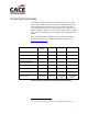
The AirPcap Product Family The AirPcap offerings are the first open, affordable and easy-to-deploy packet capture solution for Windows. All of the AirPcap offerings will capture full 802.11 data, management, and control frames that can be viewed in Wireshark thereby providing in-depth protocol dissection and analysis capabilities. Below we provide a feature matrix that gives a highlevel overview of the feature sets of the adapters in the AirPcap Product Family.
A Brief Introduction to 802.11 Terminology The terms Wireless LAN or WLAN are used to indicate a wireless local area network, e.g. a network between two or more “stations” that uses radio frequencies instead of wires for the communication. All components that can “connect” to a WLAN are referred to as stations. Stations fall into one of two categories: access points or wireless clients. Access points transmit and receive information to/from stations using radio frequencies.
18, 24, 36, 48 and 54 Mbps. 802.11i, ratified in 2004, defines an enhanced security mechanism based on AES. 802.11n, expected to be ratified in 2009, is backward compatible with 802.11a, b, and g, and will operate at 2.4 GHz and optionally 5 GHz. It can potentially support data rates up to 600 Mbps. Channels 802.11b and 802.11g divide the 2.4 GHz spectrum into 13 channels, beginning with channel 1 and ending with channel 13. The center frequency of channel 1 is 2,412MHz, channel 2 is 2,417MHz, etc.
interference and accommodate good wireless coverage using multiple BSSs. A BSS is formed by wireless clients “associating” themselves with a particular access point. Naturally, a wireless client will have to “discover” whether there is an access point within range and its corresponding channel. For this purpose, access points advertise themselves with “beacon” frames and wireless clients can (passively) listen for these frames.
The Control frames are used to improve the reliability characteristics of the link. The establishment of a BSS through the process of discovery and association is supported by the Management frames, including possible authentication steps in the process. It is beyond the scope of this brief introduction to describe the details of these frames and their usage in the 802.11 protocol. If you are interested in additional details, you can consult the following websites: http://standards.ieee.org/getieee802/802.
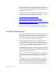
section WEP Keys on page 11 and The Decryption Keys Management Dialog on page 18 for more information. Multiple Channel Capture (applies to USB adapters only) This section applies to all members of the AirPcap Product family except AirPcap N. When listening on a single channel is not enough, multiple AirPcap adapters can be plugged in a PC and used at the same time to capture traffic simultaneously from different channels.
Configuring the Adapters: the AirPcap Control Panel The AirPcap control panel (Figure 1) provides a convenient and intuitive way to configure the parameters of currently-connected AirPcap adapters. The changes made to an adapter using the AirPcap control panel will be reflected in all of the applications using that adapter.
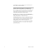
Settings The AirPcap N adapter Is Selected. Extension Channel Drop-down List for AirPcap N Figure 2: AirPcap N and Extension ChannelSetting The Basic Configuration box contains the following settings: 10 • Channel: The channels available in the Channel list box depend upon the selected adapter. Since channel numbers 1, …, 14 in the 2.4GHz and 5GHz bands overlap and there are center frequncies (channels) that do not have channels numbers, each available channel is given by its center frequency.
specification). PPI and radio information includes additional information not contained in the 802.11 frame: transmit rate, signal power, signal quality, channel, and (for PPI) multiple antenna information. Note: • Include 802.11 FCS in Frames: if checked the captured frames will include the 802.11 4-bytes Frame Check Sequence. This option can be disabled if an application has difficulty decoding the packets that have the Frame Check Sequence.
consideration, since the driver uses the keys in the order they appear in this list. The currently configured keys are shown in the “Keys” list. It is possible to turn WEP decryption on and off at any time by using the “Enable WEP Decryption” check box. Figure 3: The AirPcap Control Panel. Keys Tab. The keys are applied to the packets in the same order they appear in the keys list. Therefore, putting frequently used keys at the beginning of the list improves performance.
the traffic from all the installed USB AirPcap adapters, as if it was coming from a single device (this feature does not include traffic from the AirPcap N adapter). The Aggregator Uses the Global List of WEP Keys List of Aggregated Channels Specific Settings for the Multi-Channel Aggregator Figure 4: Multi-Channel Aggregator As Figure 4 shows, the Multi-Channel Aggregator has its own FCS, Capture Type and FCS Filter settings.
AirPcap and Wireshark The user interface of Wireshark is completely integrated with AirPcap. This increases your productivity, and allows you to get the best from the network analyzer you are used to. Identifying the AirPcap Adapters in Wireshark Figure 5 shows the Wireshark Capture Interfaces dialog (Capture→Interfaces). The AirPcap Interfaces are easly identified by icon next to them.
When Wireshark starts, the active interface is the default one (Edit→Preferences→Capture→Default Interface). During Wireshark usage, the active interface is the last one used for packet capture.
• Decryption mode: can be one of the following: o None: no decryption is performed, neither at the driver level nor in Wireshark. o Wireshark: the driver doesn’t perform any decryption of the captured packets, and they are decrypted by Wireshark while displaying them. This has the advantage of minimizing the CPU load during the capture process. Moreover, the driver doesn’t manipulate the packets, so the captured data is a precise picture of the network traffic.
Figure 7: Wireless Settings Dialog in Wireshark The parameters that can be configured are: AirPcap User’s Guide • Channel: the channels are specified in terms of their center frequencies and the range of channels varies from adapter to adapter. • Channel Offset: set to -1, 0, or +1 for AirPcap N. This allows the use of “wide” channels. • Capture Type: 802.11 frames only, or 802.11 frames plus Radio information (Radiotap header), or 802.11 frames plus the Per Packet Information (PPI) header.
The Decryption Keys Management Dialog This dialog window (shown in Figure 8) can be used to organize the keys that will be used to decrypt the wireless packets. It is possible to decrypt packets encrypted with WEP, WPA and WPA2. however, notice that: • In order to decrypt WPA and WPA2 you will need to capture the 4-way EAPOL handshake used to establish the pairwise transient key (PTK) used for a session. • Wireshark can only decrypt “WPA personal” sessions, which use pre-shared keys.
WEP keys are array of bytes of arbitrary length expressed in hexadecimal. WPA and WPA2 keys can be of two types: • Passphrase (WPA-PWD): This is the Passprase and SSID combination most often used to configure WPA and WPA2. The passphrase is a string between 8 and 63 characters in length. The SSID can be omitted, in which case Wireshark will use the lastseen SSID on the network. Non-printable characters can be represented by a “%” character followed by a hexadecimal number for both the passphrase and SSID.
Transmit Raw 802.11 Frames on Your Network For advanced users, AirPcap Tx and AirPcap Ex have the ability to inject raw 802.11 frames into your wireless network which makes them an invaluable aid in assessing the security of your wireless network. There are several freeware and open-source tools that are compatible with AirPcap Tx and AirPcap Ex. Since these tools have not been developed by CACE Technologies, it is recommended that you visit their official websites for additional information. Aircrack-ng.
Where to Learn More The best sources of information about the Wireshark network analyzer are: • The documentation page on the Wireshark website, http://www.wireshark.org/docs/. From here you can download the User’s Guide, the man pages, and the developer’s manuals. • The Wireshark wiki, http://wiki.wireshark.org/. • The Wireshark mailing lists, http://www.wireshark.org/lists/. • Wireshark University, http://www.wiresharku.com.
Appendix A: 802.11 Frequencies 2.4GHz Band 2312MHz to 2372 MHz in 5MHz steps. The 802.11b/g center frequencies and corresponding channel numbers are: (2412MHz, Channel 1) to (2472MHz, Channel 13), where the frequencies are incremented by 5MHz and the channel numbers by 1. There is an additional frequency for channel 14, namely, 2484MHz which is 12MHz beyond channel 13. All of the 2.4GHz channels are supported by all of the adapters in the AirPcap Product Family.
• 4920MHz to 4995MHz in 5MHz increments. These correspond to A channels 240 to 255. • 5000MHz to 5995MHz in 5MHz increments. These correspond to A channels 0 to 199 • 6000MHz to 6100MHz in 5 MHz increments AirPcap N AirPcap N supports a wide range of center frequencies. As usual, the channel bandwidth around each center frequency is 20MHz.