
Network Router User Manual
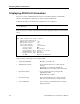
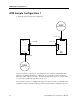
Table Of Contents
- Notices
- Contents
- About This Manual
- Introduction
- Hot Swapping Line Cards and Control Modules
- Bridging Configuration Guide
- Bridging Overview
- VLAN Overview
- Configuring SSR Bridging Functions
- Monitoring Bridging
- Configuration Examples
- SmartTRUNK Configuration Guide
- ATM Configuration Guide
- Packet-over-SONET Configuration Guide
- DHCP Configuration Guide
- IP Routing Configuration Guide
- IP Routing Protocols
- Configuring IP Interfaces and Parameters
- Configuring IP Interfaces to Ports
- Configuring IP Interfaces for a VLAN
- Specifying Ethernet Encapsulation Method
- Configuring Jumbo Frames
- Configuring Address Resolution Protocol (ARP)
- Configuring Reverse Address Resolution Protocol (RARP)
- Configuring DNS Parameters
- Configuring IP Services (ICMP)
- Configuring IP Helper
- Configuring Direct Broadcast
- Configuring Denial of Service (DOS)
- Monitoring IP Parameters
- Configuring Router Discovery
- Configuration Examples
- VRRP Configuration Guide
- RIP Configuration Guide
- OSPF Configuration Guide
- BGP Configuration Guide
- Routing Policy Configuration Guide
- Route Import and Export Policy Overview
- Configuring Simple Routing Policies
- Configuring Advanced Routing Policies
- Multicast Routing Configuration Guide
- IP Policy-Based Forwarding Configuration Guide
- Network Address Translation Configuration Guide
- Web Hosting Configuration Guide
- Overview
- Load Balancing
- Web Caching
- IPX Routing Configuration Guide
- Access Control List Configuration Guide
- Security Configuration Guide
- QoS Configuration Guide
- Performance Monitoring Guide
- RMON Configuration Guide
- LFAP Configuration Guide
- WAN Configuration Guide
- WAN Overview
- Frame Relay Overview
- Configuring Frame Relay Interfaces for the SSR
- Monitoring Frame Relay WAN Ports
- Frame Relay Port Configuration
- Point-to-Point Protocol (PPP) Overview
- Configuring PPP Interfaces
- Monitoring PPP WAN Ports
- PPP Port Configuration
- WAN Configuration Examples
- New Features Supported on Line Cards
ATM Sample Configuration 1
52 SmartSwitch Router User Reference Manual
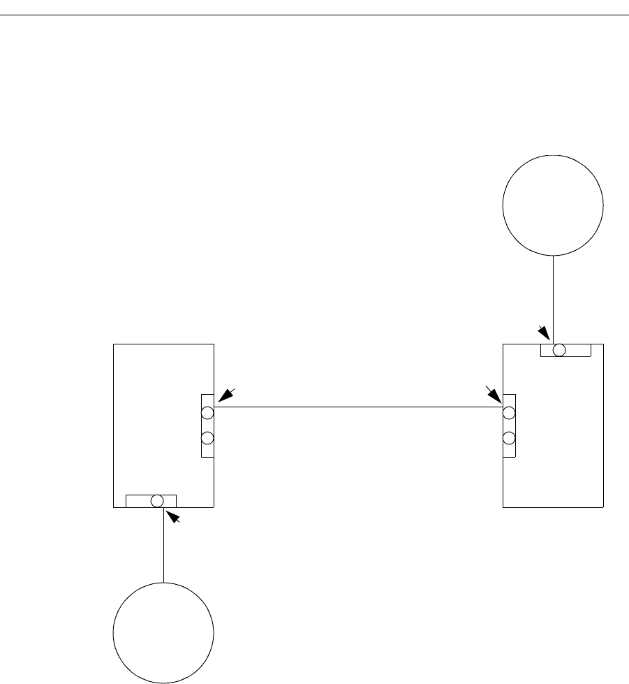
ATM Sample Configuration 1
Consider the following network configuration:
The network shown consists of two SmartSwitch Routers, VLAN A, and VLAN B. Both
SSRs have an ATM module with two ATM ports. Also both SSRs contain a 10/100 TX
Ethernet module. SSR1 is connected to VLAN A through Ethernet port et.2.1, while SSR2
is connected to VLAN B through Ethernet port et.1.1.
This example shows how to configure this network so that we are able to pass traffic from
VLAN B to VLAN A. The following steps will lead you through the configuration process.
SSR 2
SSR 1
et.1.1
et.2.1
at.1.1 at.2.1
VLAN B
VLAN A
Subnet 11.1.2.0
Subnet 11.1.1.0
11.1.1.1/24
11.1.2.1/24
11.1.100.1/24
11.1.2.1/24