
Network Router User Manual
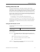
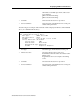
Table Of Contents
- Notices
- Contents
- About This Manual
- Introduction
- Hot Swapping Line Cards and Control Modules
- Bridging Configuration Guide
- Bridging Overview
- VLAN Overview
- Configuring SSR Bridging Functions
- Monitoring Bridging
- Configuration Examples
- SmartTRUNK Configuration Guide
- ATM Configuration Guide
- Packet-over-SONET Configuration Guide
- DHCP Configuration Guide
- IP Routing Configuration Guide
- IP Routing Protocols
- Configuring IP Interfaces and Parameters
- Configuring IP Interfaces to Ports
- Configuring IP Interfaces for a VLAN
- Specifying Ethernet Encapsulation Method
- Configuring Jumbo Frames
- Configuring Address Resolution Protocol (ARP)
- Configuring Reverse Address Resolution Protocol (RARP)
- Configuring DNS Parameters
- Configuring IP Services (ICMP)
- Configuring IP Helper
- Configuring Direct Broadcast
- Configuring Denial of Service (DOS)
- Monitoring IP Parameters
- Configuring Router Discovery
- Configuration Examples
- VRRP Configuration Guide
- RIP Configuration Guide
- OSPF Configuration Guide
- BGP Configuration Guide
- Routing Policy Configuration Guide
- Route Import and Export Policy Overview
- Configuring Simple Routing Policies
- Configuring Advanced Routing Policies
- Multicast Routing Configuration Guide
- IP Policy-Based Forwarding Configuration Guide
- Network Address Translation Configuration Guide
- Web Hosting Configuration Guide
- Overview
- Load Balancing
- Web Caching
- IPX Routing Configuration Guide
- Access Control List Configuration Guide
- Security Configuration Guide
- QoS Configuration Guide
- Performance Monitoring Guide
- RMON Configuration Guide
- LFAP Configuration Guide
- WAN Configuration Guide
- WAN Overview
- Frame Relay Overview
- Configuring Frame Relay Interfaces for the SSR
- Monitoring Frame Relay WAN Ports
- Frame Relay Port Configuration
- Point-to-Point Protocol (PPP) Overview
- Configuring PPP Interfaces
- Monitoring PPP WAN Ports
- PPP Port Configuration
- WAN Configuration Examples
- New Features Supported on Line Cards

SmartSwitch Router User Reference Manual 47
Creating a Non-Zero VPI
Creating a Non-Zero VPI
The Virtual Path Identifier defines a virtual path, a grouping of virtual channels
transmitting across the same physical connection. The actual number of virtual paths and
virtual channels available on an ATM port depends upon how many bits are allocated for
the VPI and VCI, respectively. By default, there are 0 bits allocated for VPI and 12 bits
allocated for VCI. You can specify a different allocation of bits for VPI and VCI for a port.
There are 12 bits available for each VPI/VCI pair per port. The number of bits allocated
define the amount of VPI and VCI values available. The following equations define the
number of virtual paths and virtual channels:
# of virtual paths = 2
n
; where n is the number of bits allocated for VPI
# of virtual channels = 2
(12-
n
)
; where (12-n) is the number of bits allocated for VCI
The bit allocation command allows you to set the number of bits allocated for VPI; the
remaining number of bits are allocated for VCI. Since there are only 12 bits available for
each VPI/VCI pair on an ATM port, the more bits you allocate for VPI, the fewer bits
remain for VCI.
Setting the Bit Allocation for VPI
To set the bit allocation for VPI on an ATM port, enter the following command in
Configure mode:
The following is a description of the parameter used to set the number of bits allocated for
VPI on an ATM port:
port <port list> This parameter identifies the ATM port. Specify this parameter in the
format: media.slot.port. Specify all-ports to set bit allocation on all
ports.
media Specifies the media type. This is at for ATM ports.
slot Specifies the slot number where the module is installed.
port Specifies the port number.
vpi-bits <num> This parameter sets the number of bits for VPI. Specify any number
between 1 and 11. The default is 1.
Sets the number of bits allocated
for VPI on a port.
atm set port <port list> vpi-bits <num>