
Network Router User Manual
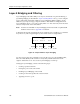


Table Of Contents
- Notices
- Contents
- About This Manual
- Introduction
- Hot Swapping Line Cards and Control Modules
- Bridging Configuration Guide
- Bridging Overview
- VLAN Overview
- Configuring SSR Bridging Functions
- Monitoring Bridging
- Configuration Examples
- SmartTRUNK Configuration Guide
- ATM Configuration Guide
- Packet-over-SONET Configuration Guide
- DHCP Configuration Guide
- IP Routing Configuration Guide
- IP Routing Protocols
- Configuring IP Interfaces and Parameters
- Configuring IP Interfaces to Ports
- Configuring IP Interfaces for a VLAN
- Specifying Ethernet Encapsulation Method
- Configuring Jumbo Frames
- Configuring Address Resolution Protocol (ARP)
- Configuring Reverse Address Resolution Protocol (RARP)
- Configuring DNS Parameters
- Configuring IP Services (ICMP)
- Configuring IP Helper
- Configuring Direct Broadcast
- Configuring Denial of Service (DOS)
- Monitoring IP Parameters
- Configuring Router Discovery
- Configuration Examples
- VRRP Configuration Guide
- RIP Configuration Guide
- OSPF Configuration Guide
- BGP Configuration Guide
- Routing Policy Configuration Guide
- Route Import and Export Policy Overview
- Configuring Simple Routing Policies
- Configuring Advanced Routing Policies
- Multicast Routing Configuration Guide
- IP Policy-Based Forwarding Configuration Guide
- Network Address Translation Configuration Guide
- Web Hosting Configuration Guide
- Overview
- Load Balancing
- Web Caching
- IPX Routing Configuration Guide
- Access Control List Configuration Guide
- Security Configuration Guide
- QoS Configuration Guide
- Performance Monitoring Guide
- RMON Configuration Guide
- LFAP Configuration Guide
- WAN Configuration Guide
- WAN Overview
- Frame Relay Overview
- Configuring Frame Relay Interfaces for the SSR
- Monitoring Frame Relay WAN Ports
- Frame Relay Port Configuration
- Point-to-Point Protocol (PPP) Overview
- Configuring PPP Interfaces
- Monitoring PPP WAN Ports
- PPP Port Configuration
- WAN Configuration Examples
- New Features Supported on Line Cards

Chapter 21: QoS Configuration Guide
292 SmartSwitch Router User Reference Manual
Within the SSR, QoS policies are used to classify Layer-2, Layer-3, and Layer-4 traffic into
the following priority queues (in order from highest priority to lowest):
• Control (for router control traffic; the remaining classes are for normal data flows)
•High
•Medium
•Low
Separate buffer space is allocated to each of these four priority queues. By default,
buffered traffic in higher priority queues is forwarded ahead of pending traffic in lower
priority queues (this is the strict priority queuing policy). During heavy loads, low-priority
traffic can be dropped to preserve the throughput of the higher-priority traffic. This
ensures that critical traffic will reach its destination even if the exit ports for the traffic are
experiencing greater-than-maximum utilization. To prevent low-priority traffic from
waiting indefinitely as higher-priority traffic is sent, you can apply the weighted fair
queuing (WFQ) queuing policy to set a minimum bandwidth for each class. You can also
apply weighted random early detection (WRED) to keep congestion of TCP traffic under
control.
Layer-2 and Layer-3 & Layer-4 Flow Specification
In the SSR, traffic classification is accomplished by mapping Layer-2, -3, or -4 traffic to one
of the four priorities. Each traffic classification is treated as an individual traffic flow in the
SSR.
For Layer-2 traffic, you can define a flow based on the following:
• MAC packet header fields, including source MAC address, destination MAC address
and VLAN IDs. A list of incoming ports can also be specified.
For Layer-3 (IP and IPX) traffic, you can define “flows”, blueprints or templates of IP and
IPX packet headers.
• The IP fields are source IP address, destination IP address, UDP/TCP source port,
UDP/TCP destination port, TOS (Type of Service), transport protocol (TCP or UDP),
and a list of incoming interfaces.
• The IPX fields are source network, source node, destination network, destination node,
source port, destination port, and a list of incoming interfaces.
For Layer-4 traffic, you can define a flow based on source/destination TCP/UDP port
number in addition to Layer-3 source/destination IP address.
The flows specify the contents of these fields. If you do not enter a value for a field, a
wildcard value (all values acceptable) is assumed for the field.