SEH-22, SEH-24, SEH-32, AND SEH-34 10BASE-T STACKABLE HUB USER’S GUIDE The Complete Networking Solution™ CABLETRON SYSTEMS, P. O.
NOTICE NOTICE Cabletron Systems reserves the right to make changes in specifications and other information contained in this document without prior notice. The reader should in all cases consult Cabletron Systems to determine whether any such changes have been made. The hardware, firmware, or software described in this manual is subject to change without notice.
NOTICE FCC NOTICE This device complies with Part 15 of the FCC rules. Operation is subject to the following two conditions: (1) this device may not cause harmful interference, and (2) this device must accept any interference received, including interference that may cause undesired operation. NOTE: This equipment has been tested and found to comply with the limits for a Class A digital device, pursuant to Part 15 of the FCC rules.
NOTICE CABLETRON SYSTEMS, INC. PROGRAM LICENSE AGREEMENT IMPORTANT: Before utilizing this product, carefully read this License Agreement. This document is an agreement between you, the end user, and Cabletron Systems, Inc. (“Cabletron”) that sets forth your rights and obligations with respect to the Cabletron software program (the “Program”) contained in this package. The Program may be contained in firmware, chips or other media.
NOTICE EXCLUSION OF WARRANTY AND DISCLAIMER OF LIABILITY 1. EXCLUSION OF WARRANTY. Except as may be specifically provided by Cabletron in writing, Cabletron makes no warranty, expressed or implied, concerning the Program (including Its documentation and media).
CONTENTS TABLE OF CONTENTS APPENDIX A CHAPTER 1 1.1 1.2 1.3 1.4 1.5 1.6 1.7 2.2 2.3 2.4 2.5 INTRODUCTION USING THIS MANUAL ............................................................ 1-1 GETTING HELP........................................................................ 1-2 SEH OVERVIEW ....................................................................... 1-2 SEH FEATURES ....................................................................... 1-3 STACKABLE CAPABILITIES ............................
CONTENTS CHAPTER 3 3.1 3.2 3.3 UNPACKING THE SEH............................................................3-1 INSTALLING THE SEH............................................................3-1 3.2.1 Stacking the SEH ..........................................................3-2 3.2.2 Attaching the Strain Relief Bracket.............................3-4 3.2.3 Rack Mounting the SEH ...............................................3-5 3.2.4 Wall Mounting the SEH................................................
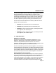
INTRODUCTION CHAPTER 1 INTRODUCTION Welcome to the Cabletron Systems SEH-22, SEH-24, SEH-32, and SEH-34 10BASE-T Stackable Hub User’s Guide. This manual explains installation instructions and provides reference information for the SEH-22, 24, 32, and 34. Note: The term SEH (Stackable Ethernet Hub) is used throughout this manual when describing features and functions that are common to the SEH-22, 24, 32, and 34. 1.
INTRODUCTION 1.2 GETTING HELP If you need additional support related to the Cabletron Systems SEH, or if you have any questions, comments, or suggestions concerning this manual, contact Cabletron Systems Technical Support: By phone ......................... (603) 332-9400 Monday-Friday; 8am - 8pm EST ® By CompuServe ............ GO CTRON from any ! prompt By Internet mail ............. support@ctron.com 1.
INTRODUCTION You can stack together up to five SEH hubs using Cabletron Systems’ external HubSTACK Interconnect cables. If you want to add management to the stack, Cabletron Systems offers the MicroMMAC and the SEHI intelligent hubs. You can stack up to four SEHs with one intelligent hub. Stackable configurations let you maintain only one IEEE repeater hop while providing up to 130 Ethernet ports. The SEH-22/24 and SEH-32/34 are functionally identical with the exception of the network ports: 1.
INTRODUCTION LANVIEW LEDs Cabletron Systems’ LANVIEW Status Monitoring and Diagnostics System is a troubleshooting tool that helps you diagnose power failures, collisions, cable faults, and link problems. The LANVIEW LEDs are conveniently located on the front panel. 1.5 STACKABLE CAPABILITIES The SEH is a non-intelligent hub designed to be managed by either the Cabletron Systems SEHI intelligent hub or the Cabletron Systems MicroMMAC intelligent hub.
INTRODUCTION Daughter Board Upgrade Kit You can upgrade the SEH-22 and the SEH-32 to 24 ports using the daughter board upgrade kit. The Cabletron part numbers for the upgrades are: • SEH-22: 24PORT-UGKT-E • SEH-32: 24PORT-UGKT-E 50P HubSTACK Interconnect Cables You need Cabletron’s HubSTACK Interconnect cables to stack hubs together. Table 1-2 lists the part number and application for each cable. Table 1-2.
INSTALLATION REQUIREMENTS/SPECIFICATIONS CHAPTER 2 INSTALLATION REQUIREMENTS/SPECIFICATIONS This chapter describes network guidelines, power requirements, and operating specifications for the SEH. Be sure to read this chapter before you install the SEH. Your network must meet the requirements and conditions specified in this chapter to obtain satisfactory performance from this equipment. Failure to follow these guidelines could result in poor network performance. 2.
INSTALLATION REQUIREMENTS/SPECIFICATIONS 2.1.2 UTP and STP Cable Specifications for the Network Ports and EPIM-T Module The device at the other end of the twisted pair segment must meet IEEE 802.3 10BASE-T specifications. When you connect a 10BASE-T Twisted Pair Segment to the SEH’s 10BASE-T Twisted Pair Network Ports and EPIM-T module, your network must meet the following requirements: Length The IEEE 802.
INSTALLATION REQUIREMENTS/SPECIFICATIONS Delay The maximum propagation delay of a 10BASE-T link segment must not exceed 1000 nsec. This 1000 nsec. maximum delay limits the maximum link segment length to no greater than 200 meters. Crosstalk Crosstalk is caused by signal coupling between the different cable pairs contained within a multi-pair cable bundle. 10BASE-T transceivers are designed so that the user does not need to be concerned about cable crosstalk, provided the cable meets all other requirements.
INSTALLATION REQUIREMENTS/SPECIFICATIONS 2.1.3 Multimode Fiber Optic Cable Specifications for the EPIM-F1 and EPIM-F2 Modules Table 2-1 shows Multimode Fiber Optic Cable specifications for the EPIM-F1 and EPIM-F2 modules. Table 2-1. Multimode Fiber Optic Cable Specifications Cable Type Attenuation Maximum Cable Length 50/125 µm 13.0 dB or less 62.5/125 µm 16.0 dB or less 100/140 µm 19.0 dB or less The maximum allowable fiber optic cable length is 2 km (2187.2 yards). However, IEEE 802.
INSTALLATION REQUIREMENTS/SPECIFICATIONS 2.1.4 Single Mode Fiber Optic Cable Specifications for the EPIM-F3 Module Table 2-2 shows Single Mode Fiber Optic Cable specifications for the EPIM-F3. Table 2-2. Single Mode Fiber Optic Cable Specifications Cable Type Attenuation Maximum Cable Length 8/125-12/125 µm 10.0 dB or less The maximum allowable fiber optic cable length is 5 km (3.1 miles) with bridges at each segment end. However, IEEE 802.3 FOIRL specifications specify a maximum of 1 km (1093.
INSTALLATION REQUIREMENTS/SPECIFICATIONS 2.1.5 Thin-net Network Requirements for the EPIM-C Module When you connect a thin-net segment to the SEH (via an EPIM-C), your network must meet the following requirements: Cable Type 50 ohm RG-58A/U type coaxial cable must be used when making up a thin-net cable segment. Length The thin-net segment must be no longer than 185 meters. Terminators A 50 ohm terminator must be connected to the far end of each thin-net segment.
INSTALLATION REQUIREMENTS/SPECIFICATIONS 2.1.6 AUI Cable Requirements for the EPIM-A and EPIM-X Modules When you connect an external network segment to the SEH (via an EPIM-A or EPIM-X), the AUI cable must meet the following requirements: AUI Cable The AUI cable connecting the module to a device must be IEEE 802.3 type cable. Length The AUI Cable must not exceed 50 meters in length. If 28 AWG thin office drop AUI cable is used, then the maximum cable length is limited to 50 feet (15.24 meters).
INSTALLATION REQUIREMENTS/SPECIFICATIONS 2.2.1 SEH-22 and SEH-24 Network Port Specifications The SEH-22 and SEH-24 provide RJ45 connections for network connections. Figure 2-1 shows the RJ45 pinouts. 12345678 12X 1. Receive + 2. Receive 3. Transmit + 4. Not Used 11X 10X 5. Not Used 6. Transmit 7. Not Used 8. Not Used Figure 2-1. RJ45 Network Ports 2.2.
INSTALLATION REQUIREMENTS/SPECIFICATIONS Table 2-3.
INSTALLATION REQUIREMENTS/SPECIFICATIONS 2.3 EPIM SPECIFICATIONS EPIMs let you connect the SEH to the main network using different media types. Cabletron Systems offers a variety of EPIMs. The following sections explain specifications for each EPIM. 2.3.1 EPIM-T The EPIM-T is an RJ45 connector supporting UTP cabling. It has an internal Cabletron Systems TPT-T™ 10BASE-T Twisted Pair Transceiver. The slide switch on the EPIM-T determines the cross-over status of the cable pairs.
INSTALLATION REQUIREMENTS/SPECIFICATIONS 2.3.2 EPIM-F1/F2 The EPIM-F1 and EPIM-F2 shown in Figure 2-4 support Multimode Fiber Optic cabling. Each EPIM has an internal Cabletron Systems FOT-F™ Fiber Optic Transceiver. The EPIM-F1 is equipped with SMA Connectors and the EPIM-F2 is equipped with ST Connectors. Specifications for the EPIMs are listed below. Figure 2-4. EPIM-F1 and EPIM-F2 Parameter Receive Sensitivity: Peak Input Power: Typical Value Worst Case Worst Case Typical Budget Budget -30.
INSTALLATION REQUIREMENTS/SPECIFICATIONS 2.3.3 EPIM-F3 The EPIM-F3 shown in Figure 2-5 supports Single Mode Fiber Optic cabling. It has an internal Cabletron Systems FOT-F™ Fiber Optic Transceiver and is equipped with ST Connectors. Specifications for the EPIM-F3 are listed below. Figure 2-5. EPIM-F3 Note: Transmitter Power decreases as temperatures rise and increases as temperatures fall. Use the Output Power Coefficient to calculate increased or decreased power output for your operating environment.
INSTALLATION REQUIREMENTS/SPECIFICATIONS Maximum Sensitivity (-36.0) Receive Sensitivity Typical Sensitivity (-31.0) Minimum Sensitivity (-30.0) Minimum Receive Input (-9.72) Typical Receive Input (-7.5) Maximum Receive Input Power Maximum Receive Input (-6.99) Maximum Transmit Power (-12.0) Transmitter Power* (At 25°C into 8.3/125µm fiber) Typical Transmit Power (-15.5) Minimum Transmit Power (-21.
INSTALLATION REQUIREMENTS/SPECIFICATIONS 2.3.4 EPIM-C The EPIM-C supports thin-net coaxial cabling and is equipped with an internal Cabletron Systems TMS-3™ Transceiver. You can use the TERM switch on the front of the EPIM-C to set the internal 50 Ohm terminator. This eliminates the need to connect the port to a tee-connector and terminator. Figure 2-6 shows the setting for the terminator switch. Internal Termination Switch = On (internally terminated) = Off (need external termination) Figure 2-6.
INSTALLATION REQUIREMENTS/SPECIFICATIONS 2.3.5 EPIM-A and EPIM-X (AUI Port) The EPIM-A is a DB15 female connector used to attach segments to an external transceiver. The EPIM-X is equipped with dual internal transceivers. It has a DB15 male connector used to attach segments to an AUI cable. Figure 2-7 shows both modules. Figure 2-7. The EPIM-A and EPIM-X DB15 Pinouts Pin 1 2 3 4 5 6 7 Logic Ref. Collision + Transmit Logic Ref.
INSTALLATION REQUIREMENTS/SPECIFICATIONS 2.4 TRANSCEIVER REQUIREMENTS When you connect an external network segment, via a transceiver, to the SEH with an EPIM-A, the following requirements must be met: 2.5 • The transceiver or Ethernet Device to which the module will be connected must meet IEEE 802.3 standards, and/or Ethernet Version 1.0 or Version 2.0 standards.
INSTALLATION REQUIREMENTS/SPECIFICATIONS JAM Output: Collisions are propagated through the network using the JAM signal of an alternating pattern of 1's and 0's in accordance with 802.3 specifications for a repeater unit. Fragment Extension: Packet fragments are extended to a minimum of 96 bits using the JAM [1,0].
INSTALLATION REQUIREMENTS/SPECIFICATIONS ENVIRONMENTAL REQUIREMENTS Operating Temperature: +5° to +50° C Non-operating Temperature: -30° to +90° C Operating Humidity: 5 to 95% (non-condensing) SAFETY This unit meets the safety requirements of UL 1950, CSA C22.2 No. 950, and EN 60950; the EMI requirements of FCC Class A and EN 55022 Class A; and the EMC requirements of EN 50082-1.
INSTALLATION CHAPTER 3 INSTALLATION This chapter outlines the procedure for installing your SEH and connecting it to a network. You can install the SEH as a stackable or stand-alone device. Ensure that your network meets the guidelines and requirements outlined in Chapter 2, Installation Requirements/Specifications, before installing the SEH. 3.1 UNPACKING THE SEH Unpack the SEH as follows: 1. Remove the shipping material covering the SEH in the shipping box. 2.
INSTALLATION Free-standing and shelf installations must be within in reach of the network cabling and meet the requirements listed below: • A single phase 120Vac, 15A, grounded power receptacle must be located within 7 feet of the location. • If you use a shelving unit, it must be able to support 30 pounds of static weight for each device in the stack. • The temperature for the selected location must be maintained between 5° and 50°C, and fluctuate less than 10°C per hour.
INSTALLATION To stack SEHs together, refer to Figure 3-1 and perform the following steps: 1. Attach the SEH HubSTACK Interconnect cable to the bus port labeled “OUT” on the rear panel of the SEH. 2. Attach the other end of SEH HubSTACK Interconnect cable to the bus port labeled “IN” on the rear panel of the SEH next in the stack. 3. Attach up to four SEH hubs in the stack repeating steps 1 and 2.
INSTALLATION If you disconnect one end of a HubSTACK Interconnect cable and leave the other end attached to the hub, ensure that you disconnect the cable from the “OUT” port as shown in Figure 3-2. This ensures that the HubSTACK Interconnect cable is terminated properly. Disconnect SEH and SEHI Interconnect Cables at the "OUT" Port.
INSTALLATION 3.2.3 Rack Mounting the SEH Refer to Figure 3-4 and perform these steps to install the SEH in a 19-inch rack. 1. Remove four cover screws (two from each side) located along the front edges of each side of the SEH. 2. Using the four cover screws removed in step 1, attach the rack mounting brackets to each end of the SEH. Rack Mounting Brackets (2) HubSTACK 10BASE-T HUB WITH LANVIEW® SEH-24 Screws (4) Figure 3-4. Installing the Rack Mount Brackets 3.
INSTALLATION 3.2.4 Wall Mounting the SEH When you wall mount the SEH, the cable connections must face down. Refer to Figure 3-6 and perform the following steps to wall mount the SEH. Note: 1/4-inch Molly screw anchors for wall mounting are not included with the SEH-ACCY-KIT package. 1. Use the supplied screws to attach the wall mounting brackets to the bottom of the SEH as shown in Figure 3-6. There are two brackets, one for each side.
INSTALLATION 3. You will need a pencil for this step. With the wall mounting brackets attached to the SEH, position the SEH against the wall where it will be permanently mounted with the network port facing down. Use the pencil to mark the wall location for the four pilot holes. 4. Set the SEH aside and carefully drill four 1/4" pilot holes, one for each of the Molly screw anchors and insert the four Molly screw anchors into the holes just drilled. 5.
INSTALLATION 3.3 CONNECTING THE SEH TO THE POWER SOURCE Note: The SEH has a universal power supply. This allows you to connect the SEH to power sources from 90 Vac to 264 Vac, 47-63 Hz. To connect the SEH to the power source: 1. Plug the power cord into the back panel of the SEH. 2. Plug the other end of the power cord into a grounded wall outlet. 3. Verify that the PWR LED is on, this indicates that the SEH is receiving power.
CONNECTING TO THE NETWORK CHAPTER 4 CONNECTING TO THE NETWORK This chapter outlines the procedure for connecting your SEH to a network. Ensure that your network meets the guidelines and requirements outlined in Chapter 2, Installation Requirements/ Specifications, before installing the SEH. 4.1 CONNECTING THE SEH TO THE NETWORK The procedure for connecting network segments to the SEH varies depending on the media and ports being connected.
CONNECTING TO THE NETWORK To connect twisted pair segments to the SEH: 1. Insert the RJ45 connector from each twisted pair segment into the desired network port on the SEH. See Figure 4-1. EPIM-2 LNK EPIM-T 18X 17X 16X X 15X 14 13X LNK EPIM-T 6X 5X 4X 3X 2X 1X EPIM-1 Figure 4-1. SEH-22/24 Network Ports 2. Check that the applicable LNK LED for the port is on. If the LED is not on, perform each of the following steps until it is: a.
CONNECTING TO THE NETWORK 4.1.2 Connecting Network Ports SEH-32 and SEH-34 The SEH-32 has a 50-pin Champ connector, while the SEH-34 has two 50-pin Champ connectors. This configuration of the SEH allows you to run a 50-pin feeder cable from the SEH to a punch down block. Each Champ connector supports 12 10BASE-T, twisted pair segments. Note: Refer to Appendix A for information about wiring the SEH to a punch down block. To connect the SEH into an existing twisted pair wiring system: 1.
CONNECTING TO THE NETWORK 4. Check that the link LED on the 10BASE-T Ethernet device and the applicable LNK LED on the SEH are on. If the LEDs are not on, perform each of the following steps until the LEDs are on: a. Check that the 10BASE-T device and the SEH have power. b. Verify the cabling between the SEH and the 10BASE-T device. c. Check the cable for continuity. If a link has not been established, contact Cabletron Systems Technical Support. 4.1.
CONNECTING TO THE NETWORK To connect an EPIM-T to a Twisted Pair Segment: 1. Insert the RJ45 connector on the twisted pair segment into the RJ45 port on the EPIM. See Figure 4-3. 2. Check that the EPIM’s LNK LED is on. If the LED is not on, perform each of the following steps until it is: a. Check that the 10BASE-T device at the other end of the twisted pair segment is powered up. b. Verify that the RJ45 connector on the twisted pair segment has the proper pinouts. c. Check the cable for continuity. d.
CONNECTING TO THE NETWORK • The physical communication link consists of two strands of fiber optic cabling: the Transmit (TX) and the Receive (RX). The Transmit strand from the applicable port on the module will be connected to the Receive port of a fiber optic Ethernet device at the other end of the segment. For example, TX of the applicable port on the module will go to RX of the other fiber optic device.
CONNECTING TO THE NETWORK F1/F2 ST Connectors F1/F2 SMA 906 Connectors w/ Half Alignment Sleeves SMA 905 Connectors F3 ST Connectors Figure 4-4. The EPIM-F1, EPIM-F2 and EPIM-F3 3. Attach the fiber labeled 2 to the applicable transmit port labeled TX, on the module. 4. At the other end of the fiber optic cable, attach the fiber labeled 1 to the transmit port of the device. 5. Attach the fiber labeled 2 to the receive port.
CONNECTING TO THE NETWORK 6. Check that the EPIM’s LNK LED is on. If the LED is not on, perform the following steps until it is: a. Check that the power is turned on for the device at the other end of the link. b. Verify proper “cross-over” of fiber strands between the applicable port on the module and the fiber optic device at the other end of the fiber optic link segment. c. Verify that the fiber connection meets the dB loss specifications outlined in Chapter 2.
CONNECTING TO THE NETWORK Note: You must terminate each segment attached to the tee-connector. If you do not attach a segment to one of the female connections on the tee-connector, then a terminator must be placed on that connection. c. Attach another thin-coax segment or a terminator to the other female connector on the tee-connector. When internal termination switch is set to off ( ): Connect BNC tee-connector to port.
CONNECTING TO THE NETWORK 4.1.6 Connecting an AUI Cable to an EPIM-A Caution: Ensure that the external transceiver to which the SEH will be connected P Wdoes not have the signal quality error (SQE or “heartbeat”) test function enabled. The SEH will not operate if the transceiver has R the SQE test function enabled, and the network will be unusable. Refer PIM-A to theEapplicable transceiver manual. To connect an EPIM-A to an external network segment: 1.
CONNECTING TO THE NETWORK 5. Check that the PWR LED on the EPIM-A is on. If the LED is not on, contact Cabletron Systems Technical Support. 6. If the PWR LED is on with the AUI cable disconnected, continue with the following checks: a. Check the AUI connections for proper pinouts. The pinouts for the transceiver connection are listed in Chapter 2. b. Check the cable for continuity. c. Reconnect the AUI cable to the SEH and the device.
CONNECTING TO THE NETWORK ON Position (Toward Back of EPIM) ON OFF OFF Position (Toward Front of EPIM) Figure 4-7. The EPIM-X 4.2 FINISHING THE INSTALLATION The SEH is now ready for operation. Before placing the network into service, test the installation thoroughly, making sure that you can address all stations and that the SEH and all stations are indicating normal operation. Ensure that the networking software is configured properly to match the installed network.
TROUBLESHOOTING CHAPTER 5 TROUBLESHOOTING This chapter contains instructions for using LANVIEW LEDs to troubleshoot physical layer network problems. 5.1 INSTALLATION CHECK-OUT After you connect the SEH to the network, verify that packets pass between all Ethernet devices connected to the SEH and any other devices connected to the network. If you encounter difficulty with any of the attached devices, check the link as follows: 1. Check that the LNK LED, if applicable, for the port is on.
TROUBLESHOOTING 2. If the remote station is ready and the LNK LED is on, but no data passes through the port, one of two conditions may exist: • Network management has disabled the port. • The port is segmented either because the collision detector was on for more than 110 µsec. or the SEH detected more than 32 consecutive collisions on the attached segment. The affected port remains segmented until a good packet is transmitted/ received without collisions.
TROUBLESHOOTING HubSTACK 10BASE-T HUB WITH LANVIEW® SEH-24 RCV LNK 24 23 22 21 20 19 18 17 16 15 14 13 PWR MGMT CLN RCV LNK 12 11 10 9 8 7 6 5 4 3 2 1 E 2 24X E 1 12X LED NAME LED COLOR DEFINITION PWR (Power) Off Green (Solid) No Power Power MGMT (Management) Green (Flashing) Off SEH Managed by an Intelligent Hub SEH Not Managed CLN (Collision) Red Collision RCV (Receive) Yellow (Flashing) Off SEH is Receiving Data No Activity LNK (Link) Green Off Link Established No Link Figure 5-
TROUBLESHOOTING CLN (Red) This LED indicates that a collision has occurred on one of the ports. RCV (Yellow Flashing) When this LED flashes, it indicates that the SEH is receiving data packets from the associated port segment.
TWISTED PAIR WIRING TABLES APPENDIX A TWISTED PAIR WIRING TABLES This appendix contains twisted pair wiring tables which will assist you if you are using a Punch Down block (see Figure A-1) to wire your twisted pair segments.
TWISTED PAIR WIRING TABLES Note: Pins 25 and 50 on Champ connector are not used. Table A-1.
TWISTED PAIR WIRING TABLES Table A-1.
TWISTED PAIR WIRING TABLES Table A-1.
TWISTED PAIR WIRING TABLES Table A-2.
TWISTED PAIR WIRING TABLES Table A-2.
TWISTED PAIR WIRING TABLES Table A-2.
TWISTED PAIR WIRING TABLES Table A-3.
TWISTED PAIR WIRING TABLES A B C D 1 2 3 4 5 6 7 8 9 10 11 12 13 14 15 16 17 18 19 20 21 22 23 24 25 26 27 28 29 30 31 32 33 34 35 36 37 38 39 40 41 42 43 44 45 46 47 48 49 50 Figure A-1.
POWER SUPPLY CORD The mains cord used with this equipment must be a 2 conductor plus ground type with minimum 0.75 mm square conductors and must incorporate a standard IEC appliance coupler on one end and a mains plug on the other end which is suitable for the use and application of the product and that is approved for use in the country of application. GERMAN: Die Netzleitung, die mit diesem Geraet benuetzt wird, soll einen zwei Leiter mit Erdleiter haben, wobei die Leiter mindestens 0.