
User`s guide


Appendix A: Specifications
Page A-2 IRM3 User’s Guide
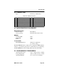
A.2 AUI PORT
Type: 15 position D type receptacle
Connector Shell: Protective Ground
A.3 FIBER OPTIC INTERFACE
Internal Transceiver: Cabletron Systems FOT-F Fiber
Optic Transceiver
Type: ST Ports
Error Rate: Better than 10
-10
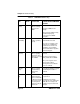
Table A-1 AUI Port Connections
Pin Signal Pin Signal Pin Signal
1 Logic Ref. 6 Power Return 11 Logic Ref.
2 Collision + 7 No Connection 12 Receive -
3 Transmit + 8 Logic Ref. 13
Power
(+12Vdc)
4 Logic Ref. 9 Collision - 14 Logic Ref.
5 Receive + 10 Transmit - 15 No Connection
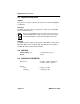
NOTE
The transmitter power levels and receive sensitivity levels
given above are Peak Power Levels after optical overshoot. A
Peak Power Meter must be used to correctly compare the
values given above to those measured on any particular port. If
Power Levels are being measured with an Average Power
Meter, then 3 dBm must be added to the measurement to
correctly compare those measured values to the values listed
above (i.e., -30.5 dBm peak=-33.5 dBm average).