7C04 Workgroup SmartSWITCH™ Chassis User’s Guide 9031700-01
Notice NOTICE Cabletron Systems reserves the right to make changes in specifications and other information contained in this document without prior notice. The reader should in all cases consult Cabletron Systems to determine whether any such changes have been made. The hardware, firmware, or software described in this manual is subject to change without notice.
Notice FCC NOTICE This device complies with Part 15 of the FCC rules. Operation is subject to the following two conditions: (1) this device may not cause harmful interference, and (2) this device must accept any interference received, including interference that may cause undesired operation. NOTE: This equipment has been tested and found to comply with the limits for a Class A digital device, pursuant to Part 15 of the FCC rules.
Notice VCCI NOTICE This equipment is in the 1st Class Category (information equipment to be used in commercial and/or industrial areas) and conforms to the standards set by the Voluntary Control Council for Interference (VCCI) by Information Technology Equipment aimed at preventing radio interference in commercial and/or industrial areas. Consequently, when used in a residential area or in an adjacent area thereto, radio interference may be caused to radios and TV receivers, etc.
CONTENTS CHAPTER 1 INTRODUCTION 1.1 USING THIS MANUAL .........................................................................1-1 1.2 USING THE SMARTSWITCH MANUAL SET ...................................1-1 1.3 CHASSIS OVERVIEW.............................................................................1-2 1.3.1 7X00 SmartSwitch Controller Module ........................................1-3 1.3.2 SmartSwitch interface modules ...................................................1-3 1.3.3 Operations............
CHAPTER 1 INTRODUCTION Welcome to Cabletron Systems 7C04 Workgroup SmartSwitch Chassis User’s Guide. This manual describes the physical characteristics, specifications, and capabilities of the 7C04 Workgroup SmartSwitch Chassis. 1.1 USING THIS MANUAL Chapter 1, Introduction, discusses the features of the 7C04 Chassis. Chapter 2, Installation, explains the 7C04 Chassis’ power supply module, and how to install that power supply module.
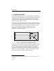
Introduction 1.3 CHASSIS OVERVIEW The 7C04 Chassis (Figure 1-1) is a rack-mountable, multi-media, switching center. The chassis is a stand-alone device that features a removable power supply. Two fans within the power supply provide system cooling. LANVIEW LEDs on the power supply indicate at-a-glance device status. The chassis has four module slots. The slots are numbered from top to bottom; the top slot is number one the bottom slot is number four.
Introduction 1.3.1 7X00 SmartSwitch Controller Module The 7X00 SmartSwitch Controller Module is the only processing and management element in the 7C04 Chassis. The 7X00 Module has no front panel data ports. All data enters and exits the 7X00 Module via the SmartSwitch Bus on the chassis’ backplane. The 7X00 Module directs incoming data to its intended destination by using a group of Application Specific Integrated Circuits (ASICs) collectively known as the SmartSwitch Core.
Introduction 1.3.3 Operations Data entering through a front panel of a SmartSwitch interface module in the 7C04 Chassis is converted by the module’s hardware into a common “canonical” format. Canonical frames are forwarded along the chassis’ SmartSwitch Bus to the 7X00 Module in slot one. The configuration of the 7X00 Module (either traditional switch or SecureFast Packet Switch) determines the manner in which frames are filtered or forwarded.
Introduction If the frame’s entry is not found in the connection table, a request is sent to the system’s Virtual Network Services (VNS). The VNS checks its virtual routing tables and policy sections.
Introduction 1.5 RELATED MANUALS The following manuals supplement the procedures and other technical data provided in this manual. The procedures will be referenced where appropriate, but will not be repeated. Cabletron Systems SmartSwitch Interface Module User’s Guides (module specific). Cabletron Systems SmartSwitch Interface Module Local Management Appendices (module specific). Cabletron Systems 7X00 SmartSwitch Controller Module User’s Guide 1.
CHAPTER 2 INSTALLATION The 7C04 Chassis can be used as a stand-alone chassis or rack mounted in a standard 19-inch equipment rack provided there is sufficient space surrounding the chassis for cooling. This chapter provides detailed information for unpacking and setting up the chassis, as well as installing and removing the chassis’ power supply module. You will not need any special tools or equipment; however, the Site Guidelines detailed in Chapter 1 must be followed. 2.
Installation 2.2 INSTALLING THE 7C04 CHASSIS IN AN EQUIPMENT RACK The following section details the process of attaching mounting brackets to the 7C04 Chassis, and installing the chassis in a standard 19-inch equipment rack. If you are not installing the chassis in an equipment rack, skip to Section 2.3. 2.2.1 Attaching Mounting Brackets An accessory package containing two mounting brackets is shipped with each 7C04 Chassis.
Installation 7. Align the two round holes of the left mounting bracket with the holes (from which you removed the screws) on the left side of the chassis. BR 8. Insert the screws that you removed in step 6 into the holes on the bracket and chassis. Tighten the screws until the mounting bracket is securely attached to the chassis. Figure 2-1.
Installation 2.2.2 Mounting the 7C04 Chassis To mount the 7C04 Chassis in a standard 19-inch equipment rack, (Figure 2-2) use the following steps: 1. Slide the chassis into the equipment rack. 2. Align the holes on the chassis’ mounting brackets with the holes on the equipment rack. 3. Insert screws (provided with the equipment rack) into the desired holes of the mounting brackets. 4. Use a screwdriver to tighten each screw until the chassis is secured to the equipment rack.
Installation 2.3 THE 7C04 CHASSIS POWER SUPPLY MODULE The 7C04 Chassis is equipped with a removable power supply module. The power supply module which is located in the right section of the chassis (Figure 2-2) operates on either 120 volts or 240 volts (AC) and automatically senses input power. The modular nature of the chassis’ power supply allows it to be easily removed and/or replaced. 2.3.1 Unpacking the Power Supply Module Unpack the power supply module by using the following steps: 1.
Installation 3. Align the notch on the top of the power supply module with the semi-circular tab in the top center of the power supply module cavity of the chassis. notch SN MAC ADR 1 2 SN SN POWER IN POWER OUT OVERLOAD FANS 3 SN 4 Figure 2-3. Installing the power supply module into a 7C04 Chassis 4. Slide the power supply module into the chassis until the power supply module connects to the chassis’ backplane and the module’s front panel is flush with the front of the chassis.
Installation 2.3.3 Powering up the Power Supply Module Note: Prior to powering up the power supply module, we recommend that you install the 7X00 Module and SmartSwitch interface modules into the chassis. Refer to the applicable module’s user’s guide for installation instructions. To power up the chassis’ power supply module, refer to Figure 2-4 and proceed as follows: 1. Plug a power cord into the power receptacle located on the front panel of the installed power supply module. 2.
Installation 2.3.4 Removing the Power Supply Module To remove the power supply module from the chassis, refer to Figure 2-4 and proceed as follows: 1. Press the power supply’s power switch to the off position (O). 2. Unplug the power cord from the power supply and from the electrical outlet. 3. Locate the knurled knob at the top center of the power supply module. 4. Loosen the knurled knob by turning it counterclockwise. 5.
CHAPTER 3 TROUBLESHOOTING The front panel of the power supply module of the 7C04 Chassis (Figure 3-1) contains four LANVIEW LEDs to assist you in troubleshooting the power supply. The color of each LED and the course of action to pursue are detailed in Table 3-1 through Table 3-4. Note: For information on the LEDs of the individual SmartSwitch interface modules, refer to each module’s user’s guide.
Troubleshooting Table 3-1. POWER IN LED LED Color Indicates Action Green The power supply’s input power is acceptable. Normal Operation. No action necessary. Red The power supply’s input power is not sufficient. Inspect the power supply’s power outlet, the power cord, and the power cord’s connection to the electrical outlet. Off The power supply has no input power. Make sure the power supply’s power switch is in the On (-) position.
Troubleshooting Table 3-3. OVERLOAD LED LED Color Indicates Action Green Normal operation No action necessary. Red The modules within the chassis are attempting to draw an amount of DC power that exceeds the power supply’s maximum DC power output. Contact Cabletron Technical Support. Table 3-4. FAN LED LED Color Indicates Action Green Normal operation No action necessary. Red One (or both) of the power supply’s fans has failed. Contact Cabletron Technical Support.
CHAPTER 4 TECHNICAL SPECIFICATIONS This chapter includes the technical specifications for Cabletron Systems 7C04 Chassis. Cabletron Systems reserves the right to change these specifications at any time without notice. 4.1 SAFETY It is the responsibility of the person who sells the chassis to ensure that the total system meets allowed limits of conducted and radiated emissions. The 7C04 Chassis meets the requirements of: • • • • UL1950 CSA C22.2 No. 950 EN60950 IEC 950 4.
Technical Specifications 4.4 SERVICE MTBF: >200,000 hours MTTR: <0.5 hour 4.5 POWER AC Input: 100 - 125 volts, 3.8 amps 200 - 250 volts, 1.9 amps 50/60 Hz DC Output: 5.1 volts 12 volts Fusing: The input of the power supply contains a 250 volt (AC) minimum fuse to protect against internal damage. This fuse is not user servicable. 4.6 PHYSICAL 4.6.1 Dimensions 34.8 D x 16.0 H x 43.2 W centimeters (13.7 D x 6.3 H x 17.0 W inches) 4.6.2 Weight 4-2 Unit: <13.5 kgs. ( <30 lbs.) Shipping: <13.
Technical Specifications 4.