R1 OPERATING INSTRUCTIONS NEWFORCE by
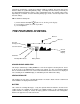
R1 - RAPID GET YOU GOING INSTRUCTIONS ASSEMBLY • Assemble stems and adjust for length. • Use the 25cm (10 inch) search head. • Twist surplus head lead around stem, allowing enough cable for free movement of the search head. (Push the cable into the cable slots in the lower stem to hold it firm). • Connect search head to detector. • Insert batteries. SET-UP • Rotate the right hand control clockwise to turn the unit on. It also acts as the volume control. Initially set it to the 3 o’clock position.
INTRODUCTION To protect your investment complete both sections of the enclosed guarantee card and return to C-Scope. This is particularly important in order to obtain the additional parts guarantee. Please retain the original packing box. In the event that your detector should ever require to be serviced, this packaging will be most suitable for postal protection. C-Scope detectors are recognised as the finest detectors available.
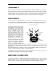
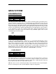
R1 A A B C D E F G H Battery Compartment Upper Stem & Handle Grips Din Plug & Socket Stem Connecting Nut Cable Lower Stem Cable Slots Search Head & Fastener B C D E F G H 3
ASSEMBLY Open the carton and remove the main housing assembly. Twist the plastic stem lock, located at the end of the upper stem to allow the lower stem to be inserted. Adjust for length and rotate the lower stem to wrap the cable around the stems and take up any slack. Allowing enough cable for free movement of the search head, push the cable into the cable slots in the lower stem to hold it firm. Turn the stem lock to fix it at the desired position.
The battery symbol gives a good representation of battery condition. This means that as the batteries drain, the symbol will gradually empty. Generally when the battery is half full you are about halfway through the charge, or life, of that battery pack. The amount of time varies depending on a number of factors including battery type, make, outside temperature and detector settings. TIP! To maximise battery life: symbol is not showing on the display.
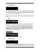
ID DISPLAY The ID, (Identifier), numbers in the lower lefthand side correspond to the position of the ID block on the line at the top of the display. When the R1 has no signal or the signal is too weak or confusing to identify the display will show ‘??’. The ID line at the top of the screen will show a block in the relative position when the R1 successfully analyses a signal. The left hand end of the display is Iron , further right is Silver paper (aluminium foil, new 10p, old 10p bottle cap and £1..
MENU SYSTEM DISCRIMINATION DISCRIM SENSITIVITY AUDIO PROGRAMS SET UP SET LEARN REJ LEARN ACC EDIT BACK This range of functions allows you to reject or ignore unwanted signals generated by items such as pull tabs. It can also act as a Notch Accept or a Notch Reject. There are four options to set the discrimination level to give maximum flexibility and ease of setting.
LEARN ACCEPT DISCRIM SENSITIVITY AUDIO PROGRAMS SET UP SET LEARN REJ LEARN ACC EDIT BACK DONE Learn Accept allows you to ‘teach’ the R1 to accept one or more targets that are swept over the search head. Once Learn Accept is selected the sample or samples are swept several times over the head. The R1 will then clear the disc setting at the sample ID point so that any objects with the same ID as the sample will be accepted. Care should be taken to ensure that you do not ‘Learn Accept’ ground, ID 0.
the MENU/SCROLL control press then ENTER button to store the setting. NOTE: This setting has no effect on the RADAR display or audio level in Pin Point mode. TIP! This level should be set as high as possible without the R1 spuriously sounding off. PIN - PT GAIN DISCRIM SENSITIVITY AUDIO PROGRAMS SET UP MOTION GAIN PIN -PT GAIN TUNE BACK This sets the sensitivity of the Pin Point, or NON-MOTION, mode. When Pin-Pt Gain is selected the R1 automatically selects Pin Point mode to aid setting the level.
PIN - PT ON This turns Audio Discrimination ON for Pin Point Mode. This gives a continuous pitch change across the entire ID range. IE a low tone for iron and a corresponding increase in pitch for more valuable metals. MOTION OFF This turns Audio Discrimination OFF for Motion Mode. MOTION ON This turns Audio Discrimination ON for Motion Mode. In this mode bad signals such as Iron will give a low tone. Good signals will give the normal tone.
The audio signal comes straight from the R1 receiver circuit. It allows the operator to listen to the true signal level and can allow the experienced user to ‘understand’ signals better. It does have the disadvantage that smaller, deeper objects give fainter signals. DIGITAL The audio signal is directly controlled by the R1 computer. In this mode the audio signal is either on or off. This means that a deep object will give the same audio volume as a shallow object.
This allows the operator to select which settings are restored when the R1 is switched on. Highlight the desired choice using the MENU/SCROLL control and then press the ENTER button. DEFAULT (setting) This will tell the R1 to load the factory default settings every time it is switched on. LAST (setting) If MANUAL mode is selected (see below) this will tell the R1 to switch on with exactly the same settings as when it was last used.
SENSITIVITY AUDIO PROGRAMS SET UP OPTIONS RECALL STORE BACK USER 2 Stores all current settings into the program selected, either USER 1 or USER 2. SETUP DISCRIM SENSITIVITY AUDIO PROGRAMS SET UP DISPLAY GROUND ADJ FREQUENCY BATTERY BACK DISPLAY DISCRIM SENSITIVITY AUDIO PROGRAMS SET UP DISPLAY GROUND ADJ FREQUENCY BATTERY BACK CONTRAST BRIGHTNESS These options allow the display settings to be adjusted.
optimum performance on a particular site. The level is adjusted by rotating the MENU/SCROLL control. An incorrect setting will result in a fluctuating signal on the RADAR display and frequent ‘0’ targets on the ID display. To find the optimum ground setting, raise and lower the head above an area of ground free from any targets then adjust the ground setting for minimum audio fluctuation and ID indications.
GENERAL HINTS Pin Pointing Move the search head to one side of the target. Press and hold the Pin Point button. Sweep the search head over the target slowly whilst monitoring the RADAR display. The target is directly below the centre of the search head when the signal is largest. If the RADAR signal is too broad then either move the head closer to the target and release and press the Pin Point button, or simply raise the search head slightly off of the ground whilst sweeping the head over the target.
Determining the Target Size An operator who is familiar with their instrument will be able to do an excellent job of determining object size, shape and depth before he digs. This technique is learned from careful analysis of the RADAR and audio signal coming from the detector. Each time a signal is heard, listen for any peculiar characteristics it may have, determine over how large an area you get a detector signal, and try to 'outline' the object before you dig.
Specification Battery Type: Supply Voltage: Supply Current: 8 x AA, MN1500 or equivalent, Alkaline cells recommended. 12v DC (nominal), 13.8v DC (max) 55mA (no backlight) 100mA (backlight full on) Battery Life: 40 Hours normal detecting using Alkaline batteries and no backlight Battery Indicator: Alkaline: Rechargeable: Audio Frequency: Full 13.2V Full 10.8V Empty 8.5V Empty 8.5V 100Hz to 5.5kHz, 714Hz (nominal) Transmit frequency: 6.097kHz, 6.250kHz, 6.
MENU STRUCTURE DISCRIMination SET LEARN REJect LEARN ACCept EDIT SENSITIVITY MOTION GAIN PIN PoinT GAIN TUNE AUDIO DISCRIMination PIN PoinT OFF PIN PoinT ON MOTION OFF MOTION ON SILent SEARCH OFF ON MODE ANALOG DIGITAL PROGRAMS GRouND TYPE INLAND BEACH OPTIONS DEFAULT LAST RECALL COIN INLAND PROGRAM ALL METAL PROGRAM COIN BEACH PROGRAM USER PROGRAM 1 USER PROGRAM 2 STORE USER PROGRAM 1 USER PROGRAM 2 SETUP DISPLAY CONTRAST BRIGHTNESS GROUND ADJust FREQUENCY LOW MIDDLE HIGH BATTERY RECHARGEABLE ALKALINE 18
OPTIONAL ACCESSORIES from C-Scope Headphones: Headphones not only extend battery life but also improve sensitivity by reducing external noises. The headphones should be fitted with a standard stereo 6.35mm, (1/4 inch), jack plug. The headphone socket is located under the protective cap in the battery housing. (NOTE: Stereo mode must be selected on headphones fitted with a stereo/mono switch).
THE IMPORTANCE OF THE RIGHT APPROACH Treasure hunting can be a profitable and rewarding hobby, if approached in a patient and diligent manner. Time spent researching to locate a worthwhile site for a search can be time wasted if your search is hasty and erratic. To achieve maximum results it is important then, to decide on your approach to any particular site in advance of the actual search.
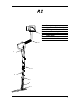
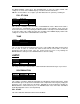
The technique of getting the best out of your detector is not learnt overnight. You need to get as much experience as possible so that you can recognise every kind of signal. Indeed, a good detector operator can often tell you what is being detected before it is unearthed. Search Head Position It is essential that the search head is kept close and parallel to the ground as in B. Do not hold the search head too high above the ground, or at an odd angle as in A, C, D as you will be apt to miss finds.
CODE OF CONDUCT 1. Do not trespass. Obtain permission before venturing on to any private land. 2. Respect the Country Code. Do not leave gates open when crossing fields, and do not damage crops or frighten animals. 3. Do not leave a mess. It is simple to extract a coin or other small objects buried a few inches under the ground without digging a great hole.
TROUBLESHOOTING (a) (b) (c) Check the condition of batteries under load using the battery monitor symbol. (See Battery Check Procedure). Check that the search head is properly attached to the control box via the search head cable connector. Interchange batteries and ensure batteries are correctly seated in the holder and that the battery connector is securely attached to the battery holder. Oscillating Signal (a) (b) (c) This could be due to poor battery connections.
Further Information If you experience any difficulty in operating your R1 or have any questions on the information in your R1 Operating Instructions Manual, please do not hesitate to phone our Customer Service Department on +44 (0)1233 629181 or e-mail: info@cscope.co.uk Before returning a detector for repair to C-Scope ensure you have done the following:(a) (b) (c) 24 Read the instructions thoroughly. Tried new batteries and checked procedure outlined above.
This equipment conforms to the EMC Directive 89/336/EEC. System performance may be impaired by unusually strong electromagnetic fields. Kingsnorth Technology Park, Wotton Road, Ashford, Kent TN23 6LN United Kingdom Telephone: +44 (0) 1233 629181 Fax: +44 (0) 1233 645897 email: info@cscope.co.uk, web: www.cscope.co.uk Pt No.