
Installation guide

Programming with the PicoScope 4000 Series (A API)6
Copyright © 2008-2014 Pico Technology Ltd. All rights reserved.ps4000apg.en r1
3.3
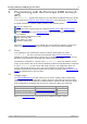
Channel selection
You can switch each channel on and off, and set its coupling mode to either AC or DC,
using the ps4000aSetChannel function.
DC coupling:
The scope accepts all input frequencies from zero (DC) up to its
maximum analog bandwidth.
AC coupling:
The scope accepts input frequencies from a few hertz up to its
maximum analog bandwidth. The lower –3dB cutoff frequency is
about 1 hertz.
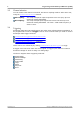
3.4
Triggering
PicoScope 4000 Series PC Oscilloscopes can either start collecting data immediately, or
be programmed to wait for a trigger event to occur. In both cases you need to use the
PicoScope 4000 trigger functions:
ps4000aSetTriggerChannelConditions
ps4000aSetTriggerChannelDirections
ps4000aSetTriggerChannelProperties
ps4000aSetTriggerDelay (optional)
These can be run collectively by calling ps4000aSetSimpleTrigger, or singly.
A trigger event can occur when one of the signal or trigger input channels crosses a
threshold voltage on either a rising or a falling edge.
The driver supports these triggering methods:
Simple Edge
Advanced Edge
Windowing
Pulse width
Logic
Delay
Drop-out
Runt