OPERATING INSTRUCTIONS 1
CS4ZX - RAPID GET YOU GOING INSTRUCTIONS Look for the highlighted pre-set positions 1. Assemble and adjust for length (Twist surplus lead around stem). 2. Insert batteries. 3. Set MODE SELECT (trigger switch) to MOTION (away from your body). 4. Set DISC (top left) to ALL METAL (fully anticlockwise). 5. Set NOTCH (bottom far left) to OFF (fully anticlockwise). 6. Set SENSITIVITY (top right) to white marker (3 o'clock position). 7.
CONTENTS: PAGE INTRODUCTION ASSEMBLY BATTERIES BATTERY CHECK GETTING TO KNOW YOUR CS4ZX CONTROLS CHANGING MODES OPERATING IN MOTION MODE OPERATING IN NON MOTION MODE DETECTION RANGE DETERMINING THE TARGET SIZE AND DEPTH ACCESSORIES (OPTIONAL) CHARGING BATTERIES THE IMPORTANCE OF THE RIGHT APPROACH SWEEPING TECHNIQUE METAL DETECTING AND THE ENGLISH LAW CODE OF CONDUCT FOR METAL DETECTOR USERS CARE OF YOUR DETECTOR DETECTOR NOT OPERATING? 4 4 4 5 6 8 11 12 15 16 16 16 16 17 18 19 19 20 20 3
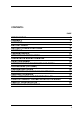
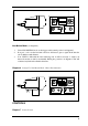
Controls C-Scope CS4ZX J A K L T S CS4ZX M N O P Q R B C I A B C D E F G H I D J E H K L M N F G O P Q R Diagram 1 4 S T Battery Compartment Din Plug & Socket Upper Stem & Handle Grips Stem Connecting Nut Lower Stem Search Head Lugs Search Head Fastener Cable Frequency Select Switch (Both Modes) All Metal Mode/Discrimination (Motion Mode) Meter (Both Modes) Power On/Off & Sensitivity Notch Discrimination (Motion Mode) Notch Discrimination Accept/Reject (Motion Mode) Mode Select Meter
INTRODUCTION To protect your investment complete both sections of the enclosed guarantee card and return the reply paid portion to C-Scope. This is particularly important in order to obtain the free second year parts guarantee. Please retain the original packing box. In the event that your detector should ever require to be serviced, this package will be most suitable for postal protection. C-Scope detectors are recognised as the finest detectors available.
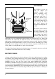
BATTERIES CHARGER HEADPHONE SOCKET SOCKET The CS4ZX is powered by eight AA batteries (not supplied) available from garages, department stores, etc. or a single 12v rechargeable pack from CScope. It is advisable to use standard batteries to start with. You can then evaluate the sort of use you give the detector and decide whether the investment in rechargeables is justified. The batteries should be fitted in the holder which is located in BATTERY COMPARTMENT the battery compartment.
Diagram 3 Checking The Batteries CS4ZX HOLD GETTING TO KNOW YOUR CS4ZX The CS4ZX has two modes of operation, Motion and Non Motion. In Motion mode the detector head must be moving for the detector to register a find. Motion has the advantage of automatic ground cancellation and simplicity of operation. Non motion mode allows greater performance in restricted areas such as in undergrowth and allows accurate pin pointing of targets.
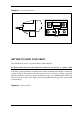
Motion Non Motion Hold Tune/Retune Push the switch forward to operate in MOTION mode, leave in the central position to operate NON MOTION and pull back and release to RETUNE in NON MOTION and to recentralise the meter. You will see the control panel on the front of the detector has been grouped into boxes. The DISC and NOTCH controls and the NOTCH switch are functional when the detector is in MOTION mode only. The GROUND control and switch are functional in the NON MOTION mode.
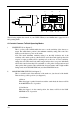
ALL METAL CS4ZX METER DISC 2 1 OFF Non Motion Mode (see diagram 6): 1. 2. 3. Select NON MOTION mode on the trigger switch (central position 3 in diagram 6). Now pass a coin over the head and notice how the detector gives a signal all the time the coin is within a certain distance. Your CS4ZX is built with the latest technology but it will be necessary to retune your detector from time to time by momentarily flicking into postition 1 in diagram 6.
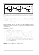
J K L I CS4ZX O M N O P Q R The following explains the controls of your CS4ZX. When you are familiar turn to page 12-15 for full operating details. A. Controls Common To Both Operating Modes i. SENSITIVITY (L in diagram 7). This is a rotary control which enables the user to set the sensitivity of the detector to targets. The anticlockwise position is the minimum sensitivity setting. This control also functions as the detector power on/off switch.
When the trigger is pulled back towards the user, the NON MOTION mode will be 'retuned'. Note that this position on the switch is 'spring loaded', i.e. to maintain RETUNE, the trigger lever must be held in this position. iii. FREQUENCY SHIFT SWITCH (I in diagram 7). This three position switch found on the rear of the main case, close to the search head connector (diagram 8) allows the user to slightly change the operating frequency of the detector.
This control allows the user to optimise the detector for use on each site. This is achieved by reducing the effect of natural mineralisation sometimes found in the ground, but it must be individually set for each ground type. In high performance detectors, like your CS4ZX, mastering this control is essential to gain the full capabilities. The range provided should allow accurate setting to exclude from the most neutral ground through to more 'mineralised' ground.
adjustment of the GROUND control in NON MOTION mode (see page 15 for further details). Once correctly set this control can be returned to METER DISC (a). c. BATTERY In this position, the meter indicates the state of charge of the batteries. When the needle is in the green area, the batteries are in a good usable condition. If the needle is in the centre or to the left of centre, the batteries are exhausted.
CHANGING MODES Switching from one mode to another is done by operating the trigger switch (O in diagram 7). Away from the body to select MOTION and central to select NON MOTION. OPERATING IN MOTION MODE Push the trigger switch forward to select MOTION mode and turn the SENSITIVITY to the highlighted area. Your CS4ZX, in MOTION mode, is now ready to use. DISC Discrimination allows the user to ignore certain metals whilst still finding others.
adjusting the REJECT NOTCH control slowly. Repeat this until no sound is emitted. The NOTCH cannot work on the deepest targets so to eliminate the response from ring pulls totally then the SENSITIVITY must also be reduced slightly. NOTCH ACCEPT works in the same way except a small band of targets are detected and all others are ignored. Now set DISC at 5 to ignore iron, etc. Please note the following: i) ii) iii) iv) Always set the NOTCH with the DISC control in ALL METAL.
Diagram 12 continued NAIL SMALL MILK HORSESHOE BOTTLE TOP 5p COIN RING PULL £1 COIN NO SOUND ACCEPT NOTCH SETTING OFF 2 4 Although the CS4ZX is manufactured to the highest specification, slight variations can occur in all electronic equipment. This chart, therefore is intended as a guide only and precise setting for maximum performance will be achieved by constant practice. How to use diagrams 10,11 and 12: If you wished to avoid detecting ring pulls and small ferrous objects (e.g.
ACCEPT 'window'. This can give the impression that the detector is not functioning correctly. It is simply remedied by switching to the highlighted REJECT position. OPERATING IN NON MOTION MODE Setting The Ground Control On Inland Sites Prior to searching, the detector must first be set to ignore the signal due to the ground mineralisation. To do this find an area of ground thought to be free of metal objects and check using MOTION mode. Then proceed as follows: 1.
area of response, deep targets give a broad response whilst shallow targets tend to be narrower. The ability to distinguish between good targets and deep iron comes with practice. Searching On A Beach The range of soil types is greater on the beach ranging from dry sand which shows very little ground effect to salty water which exhibits severe mineralisation. To accommodate this range the GROUND switch must be put into BEACH. The GROUND control is then adjusted as described above for the INLAND site.
ACCESSORIES (OPTIONAL) Available from C-Scope Headphones: Headphones not only extend battery life but improve sensitivity by cutting extraneous noise. The headphones should be fitted with a standard stereo 1/4 inch (6.35mm) jack plug. The headphone socket is located under the protective cap in the battery housing. Mini searchhead: The mini searchhead can be used in place of the supplied head for searching in heavily trashed sites. The depth penetration is reduced slightly.
Tactics will be decided by the type of site - it is more profitable to scan a small area thoroughly than to conduct a haphazard search of the total site. However, when the site is too far away for you to make several return visits, a plan should be adopted which gives maximum coverage, at the same time as indicating the most likely area for detailed search. Your detector alone is not a guarantee of successful treasure hunting.
Diagram 13 Search Head Position A B C D It is essential that the search head is kept close and parallel to the ground as in B. Do not hold the search head too high above the ground, or at an odd angle as in A, C, D as you will be apt to miss finds. SWEEPING TECHNIQUE For extremely small object searching, such as coins, rings, nuggets, etc. lower the search coil to within 1 inch of the ground. Sweeping the coil from side to side in a straight line in front of you.
In the event of the Police failing to locate the owner they will probably return the object to the finder. If, however, the owner makes a claim for the object at a later date, the finder must return the item to the owner. If the owner is not located the finder has the best rights to ownership, provided that the object was not found on private property, in which case the owner of the land has a better right than the finder.
from the Historic Buildings and Ancient Monument Commission for England or the Secretary of State for the Environment in Scotland and Wales. 8. Remember that when you are out with your metal detector, you are an ambassador for our hobby. Do nothing that may give it a bad name. CARE OF YOUR DETECTOR Storage When not in use your detector should be stored in a dry warm environment.
(a) Temperature drift caused by change in air temperature when a machine is moved from a house or car into the open. The greater the change in temperature the more the drift, and in severe conditions up to 30 minutes may be needed for the electronic circuitry to acclimatise itself. (b) Sometimes battery drain can cause drift of signal. Replace batteries and this should help to maintain a stable signal.
Kingsnorth Technology Park, Wotton Road, Ashford, Kent TN23 2LN Telephone: (0233) 629181 Fax: (0233) 645897 Issue 3 (1/94) 25