
Instruction Manual

SIGHT MODELS:
Voice - 540-347-4683
Fax - 540-347-4684
e-mail - sales@cmore.com
web - www.cmore.com
CMS-IB-RTS2R-111813
PLEASE read instructions before operating
or installing this sighting system.
PACKAGE CONTENTS:
1 - RTS2R Sight 1 - Wrench - Mounting screws
1 - RTS2MT-200 Mount for Rail Mount
(Attached) 1 - Wrench - Rail Clamp
1 - Cover 1 - Wrench - Direct Mounting
1 - Instruction Manual Screws
1 - Adjustment Wrench 2 - Direct Mounting Screws
Instruction Manual
© C-MORE Systems 1993-2013
Congratulations! You are now the owner of the most
advanced reflex sighting system available. You have dis-
played excellent judgement in your purchase, and you will
be rewarded with unparalleled performance. Use it with
pride, but please familiarize yourself with the system first.
RTS2RB-3
RTS2RB-6
RTS2R
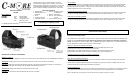
DESCRIPTION OF MAJOR COMPONENTS
INTENSITY
SWITCH
Used to set the intensity (Brightness) of the dot or turn the dot off. The RTS2R provides 10 visible brightness settings.
Turning ON: Pressing either the up or down button will turn the dot on to the previously set intesity.
Adjusting: Pressing the UP button will adjust the intensity of the dot UP incrementally to position 10. Pressing the
DOWN button will adjust the intensity of the dot DOWN incrementally to position 1.
Turning OFF: Holding either button for 3 seconds will turn the dot off.
Auto OFF: The dot will turn OFF automatically after 8 hours of inactivity.
WINDAGE ADJUSTMENT SCREW
Used when zeroing weapon. Turning the windage adjustment screw clockwise moves the point of impact right.
Turning the windage adjustment screw counter-clockwise moves the point of impact left. (1 click = 1moa)
LOCK SCREW
Used to lock the elevation and windage adjustment mechanism once the sight has been zeroed to the weapon.
Turning the lock screw counter-clockwise one and a half turns will loosen the screw and allow elevation and
windage adjustments to be made. Turning the lock screw clockwise until firmly snug will lock the elevation and
windage adjustments in their current location.
ELEVA
TION ADJUSTMENT SCREW
Used when zeroing weapon. Turning the elevation adjustment screw clockwise moves the point of impact down.
Turning the elevation adjustment screw counter-clockwise moves the point of impact up. (1 click = 1moa)
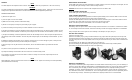
INSTALLATION INSTRUCTIONS
The RTS2R sight can be installed on any Picatinny or Weaver rail style scope mount by utilizing the RTS2MT-200
Rail Mount provided (Rail mount is NOT shipped fully tightened to the sight! Follow mounting instructions
below). The RTS2R can also be installed using a C-MORE STS mount or mounting kit, or it can be installed direct-
ly to an aftermarket or custom mount using the screws provided.
Picatinny or Weaver rail installation instructions:
1) Remove the 2 mounting screws that attach the RTS2MT-200 Rail Mount to the sight.
2) Degrease the screws and the mounting holes in the base.
3) Apply Blue Loctite #243 thread locker to the threads in the mounting holes in the base.
4) Re-Install the mounting screws and tighten until firmly snug. (Do Not Overtighten)
C-MORE STS mount or mounting kit installation instructions:
Follow the instructions provided with the mount or mounting kit.
Direct Mounting installation instructions:
Follow the instructions provided with the mount or mounting kit, or utilize the direct mounting screws provided.
NOTE: Do Not Overtighten Mounting Screws! If the battery tray cannot be removed / installed freely, then the
mounting screws are too tight causing the battery tray to bind.
Mounting Maintenance:
Periodically check the sight to ensure that it is firmly mounted and there is no movement. If movement is detected,
or mounting screws have loosened, remove the mounting screws and re-apply loctite prior to re-installation.
Firing a weapon with a loose sight can cause damage to the weapon, the sight, and you!
STOP!! Make sure your firearm is unloaded and the magazine and ammunition has been
removed before proceeding!