
Instruction Manual


SIGHT MODELS:
Voice - 540-347-4683
Fax - 540-347-4684
e-mail - sales@cmore.com
web - www.cmore.com
PLEASE read instructions before operating
or installing this sighting system.
PACKAGE CONTENTS:
1 - RTS2B Sight 2 - Direct Mounting Screws
1 - Cover 1 - Wrench - Direct Mounting
1 - Instruction Manual Screws
1 - Adjustment Wrench
Instruction Manual
© C-MORE Systems 1993-2019
Congratulations! You are now the owner of the most
advanced reflex sighting system available. You have dis-
played excellent judgement in your purchase, and you will
be rewarded with unparalleled performance. Use it with
pride, but please familiarize yourself with the system first.
RTS2B-3
RTS2B-6
RTS2B-8
RTS2B-10
RTS2B - V5
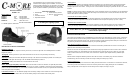
DESCRIPTION OF MAJOR COMPONENTS
INTENSITY SWITCH
Used to turn the sight ON, adjust the intensity of the dot, and turn the sight OFF. The RTS2B provides 10 visible
brightness settings.
T
urning ON
: Pressing either the up or down button will turn the dot on to the previously set intensity.
Adjusting: Pressing the UP button will adjust the intensity of the dot UP incrementally to position 10. Pressing the
DOWN button will adjust the intensity of the dot DOWN incrementally to position 1.
Turning OFF: Holding either button for 3 seconds will turn the dot off.
Motion Sensing System (MSS) / Auto OFF: After 3 minutes with no motion or vibration, the sight will power down
the Dot and enter standby mode to save battery life. Once any motion or vibration is detected, the sight will instantly
power on the Dot for immediate use. If no motion or vibration is detected after 4 hours, the sight will enter AUTO OFF
mode and power down completely.
Low Battery Indicator: The dot will flash rapidly when the battery voltage cannot sustain the current intensity level.
Lowering the intensity will allow further use until the battery voltage cannot sustain that intensity level.
WINDAGE ADJUSTMENT SCREW
Used when zeroing weapon. Turning the windage adjustment screw clockwise moves the point of impact right.
Turning the windage adjustment screw counter-clockwise moves the point of impact left. (1 click = 1moa)
LOCK SCREW
Used to lock the elevation and windage adjustment mechanism once the sight has been zeroed to the weapon.
Turning the lock screw counter-clockwise one and a half turns will loosen the screw and allow elevation and
windage adjustments to be made. Turning the lock screw clockwise until firmly snug will lock the dot in its current
location.
NOTE: The locking screw locks the dot/diode plate, not the adjustment screws. It is possible to turn the adjustment
screws a few clicks in either direction when the locking screw is locked, this is normal, but shouldn’t be done. The
detents will hold the screws in position.
ELEVATION
ADJUSTMENT SCREW
Used when zeroing weapon. Turning the elevation adjustment screw clockwise moves the point of impact down.
Turning the elevation adjustment screw counter-clockwise moves the point of impact up. (1 click = 1moa)
INSTALLATION INSTRUCTIONS
The RTS2 can be installed using a C-MORE mount or mounting kit, an aftermarket or custom mount, or directly to
the firearm with the correct mounting interface machined into the slide or barrel depending on the firearm, or an
OEM plate system designed for this sight. The direct mounting screws provided (8-32 threads) are a standard 1/2”
long and may needed to be trimmed to length for your specific application.
Direct Mounting installation instructions:
The sight must be mounted on a flat surface. Follow the instructions provided with the mount or mounting kit, or
utilize the direct mounting screws provided.
NOTE: Do not mount the sight with the front or back of the body tight against the mount or slide. There should be
a minimum clearance of .025” between the front and back of the sight and the mount or slide cut. If the sight
shows contact marks on the front or back, more clearance is required. Sight footprint drawing available upon
request.
NOTE: Do Not Overtighten Mounting Screws! 25 in-lbs max torque. If the battery tray cannot be removed /
installed freely, then the mounting screws are too tight causing the battery tray to bind.
Mounting Maintenance:
Periodically check the sight to ensure that it is firmly mounted and there is no movement. If movement is detected,
or mounting screws have loosened, remove the mounting screws and re-apply loctite prior to re-installation.
Firing a weapon with a loose sight can cause damage to the weapon, the sight, and you!
STOP!! Make sure your firearm is unloaded and the magazine and ammunition has been
removed before proceeding!
CMS-IB-RTS2B-080619