
Instruction Booklet

RAILWAY
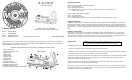
Railway Models: RW, CRW, ARW
Tactical Railway Models: TRW, CTRW, ATRW
C-MORE Systems
Voice - 703-361-2663
Fax - 703-361-5881
e-mail - sales@cmore.com
web - www.cmore.com
CMS-IB-RW-041608
Congratulations! You are now the owner of the most advanced reflex sighting system available. You have displayed
excellent judgement in your purchase, and you will be rewarded with unparalleled performance. Use it with pride, but
please familiarize yourself with the system first.
PLEASE read instructions before operating or installing this sighting system.
INSTALLATION
The Railway sight can be installed on most Picatinny (MIL-Std 1913) and Weaver style mounts.
1) Loosen the Clamp Screws two revolutions with the Torx Wrench provided.
2) Position the sight on top of the Picatinny or Weaver Rail and align the front clamp screw so it can fall into the
nearest slot, then slide the rear clamp screw into the rear most available slot.
3) Insert the long arm of the Torx Wrench into the clamp screws and tighten them until the clamps start to tighten
around the rail. Before the sight is snug, push it forward on the rail to take up the slack and then continue to
tighten until the clamp screws are just snug.
4) Once the screws are snug, insert the short arm of the wrench into the clamp screws and tighten them an
additional 1/4 to 3/8 of a turn. DO NOT OVERTIGHTEN!!
After 10-25 rounds have been fired, check to ensure the sight is still tight on the rail and re-tighten if necessary.
If the sight is mounted on a large caliber firearm, it may be necessary to purchase an additional clamp set and
install into the center slot on the Railway Base.
INTENSITY SWITCHES
C-MORE sighting systems are available with two switch styles, standard and click adjustable. The standard is a
dial rheostat switch with a continuous adjustment through the wide intensity range. The click adjustable switch
has 12 positions. The first position is off and the second and third are for night vision (low / high) and are not vis-
ible. Positions 4 - 12 are the visible intensity settings giving you a wide range of adjustment for any lighting con-
dition.
INTENSITY ADJUSTMENT
The intensity of the dot needs to be adjusted to the lighting condition in the operating area. The dot should
appear bright but not glaring. For example, outside in bright sunlight you will most likely use the brightest set-
ting, while at dawn or dusk, or indoors you will need to use one of the lower settings. The first two positions on
the click switch are extremely dim and can only be seen through a Night Vision device.
PACKAGE CONTENTS
Models - RW, CRW, TRW, CTRW (Polymer Bodies)
Qty 1 - Instruction Manual
Qty 1 - Railway Red Dot Sight
Qty 1 - Hardware Pack = (1) Hex Wrench 1/16, (1) Hex Wrench 5/64, (1) Torx Wrench T20,
(2) Extra Cover Screws
Models - ARW, ATRW (Aluminum Bodies)
Qty 1 - Instruction Manual
Qty 1 - Railway Red Dot Sight
Qty 1 - Hardware Pack = (1) Hex Wrench 1/16, (1) Torx Wrench T20, (2) Extra Cover Screws
1
2
3
4
5
6
7
7
8
9
10
11
12
Instruction Manual
© C-MORE Systems 1993-2008
13
(Tactical Railway)
1.Beam Splitter Lens
2.Elevation Adjustment Screw
3.Battery Cover
4.Diode Cover
5.Diode Module
6.Intensity Switch
7.Clamp Screw
8.Railway Base
9.Windage Guide Pin
10.Elevation Locking Screw
11.Windage Adjustment Screw
12.Windage Locking Screw
13.Tactical Spacer Plate (Tactical Railway Only)
STOP!! Make sure your firearm is unloaded and the magazine
and ammunition has been removed before proceeding!