
Instruction Manual

www.vishay.com For technical questions within your region, please contact one of the following: Document Number: 94549
2 DiodesAmericas@vishay.com
, DiodesAsia@vishay.com, DiodesEurope@vishay.com Revision: 19-May-10
VSKDU300/06PbF
Vishay Semiconductors
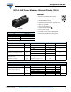
INT-A-PAK Power Modules
Ultrafast Diodes, 300 A
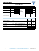
DYNAMIC RECOVERY CHARACTERISTICS (T
J
= 25 °C unless otherwise specified)
PARAMETER SYMBOL TEST CONDITIONS MIN. TYP. MAX. UNITS
Reverse recovery time t
rr
T
J
= 25 °C
I
F
= 50 A
dI/dt = 200 A/μs
V
R
= 400 V (per leg)
- 130 165
ns
T
J
= 125 °C - 195 260
Peak recovery current I
rr
T
J
= 25 °C - 11 18
A
T
J
= 125 °C - 20 30
Reverse recovery charge Q
rr
T
J
= 25 °C - 670 1485
nC
T
J
= 125 °C - 1800 3900
Peak rate of recovery current dI
(rec)M
/dt T
J
= 125 °C - - 400 A/μs
Softness factor per leg s
I
F
= 50 A, T
J
= 25 °C, dI/dt = 400 A/μs, V
R
= 200 V - 0.2 -
I
F
= 50 A, T
J
= 125 °C, dI/dt = 400 A/μs, V
R
= 200 V - 0.22 -
THERMAL AND MECHANICAL SPECIFICATIONS
PARAMETER SYMBOL TEST CONDITIONS VALUES UNITS
Maximum junction operating and
storage temperature range
T
J
, T
Stg
- 40 to 150 °C
Maximum thermal resistance,
junction to case per leg
R
thJC
DC operation 0.16
K/W
Typical thermal resistance,
case to heatsink
R
thCS
Mounting surface, flat, smooth and greased 0.05
Mounting
torque ± 10 %
to heatsink
A mounting compound is recommended and the
torque should be rechecked after a period of 3 hours
to allow the spread of the compound.
4 to 6 Nm
busbar
Approximate weight
200 g
7.1 oz.
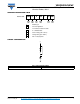
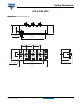
Case style INT-A-PAK