
Instruction Manual

Document Number: 94549 For technical questions within your region, please contact one of the following: www.vishay.com
Revision: 19-May-10 DiodesAmericas@vishay.com
, DiodesAsia@vishay.com, DiodesEurope@vishay.com 1
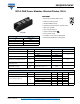
INT-A-PAK Power Modules Ultrafast Diodes, 300 A
VSKDU300/06PbF
Vishay Semiconductors
FEATURES
• Electrically insulated by DBC ceramic
• 3500 V
RMS
isolating voltage
• Standard JEDEC package
• Simplified mechanical designs, rapid assembly
• High surge capability
• Large creepage distances
• UL approved file E78996
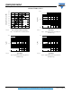
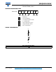
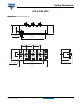
• Case style INT-A-PAK
• Compliant to RoHS directive 2002/95/EC
• Designed and qualified for industrial level
PRODUCT SUMMARY
I
F(AV)
at T
C
300 A at 48 °C
V
R
600 V
t
rr
(typical) 130 ns
I
F(DC)
at T
C
230 A at 100 °C
INT-A-PAK
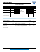
ABSOLUTE MAXIMUM RATINGS
PARAMETER SYMBOL TEST CONDITIONS VALUES UNITS
Cathode to anode voltage V
R
600 V
Continuous forward current per leg I
F
T
C
= 25 °C 435
AT
C
= 100 °C 230
Single pulse forward current I
FSM
Limited by junction temperature TBD
Maximum power dissipation per leg P
D
T
C
= 25 °C 781
W
T
C
= 100 °C 313
Operating junction and storage
temperature range
T
J
, T
Stg
- 40 to 150 °C
RMS insulation voltage V
INS
50 Hz, circuit to base,
all terminals shorted, t = 1 s
3500 V
ELECTRICAL SPECIFICATIONS (T
J
= 25 °C unless otherwise specified)
PARAMETER SYMBOL TEST CONDITIONS MIN. TYP. MAX. UNITS
Cathode to anode breakdown voltage V
BR
I
R
= 500 μA 600 - -
V
Forward voltage drop per leg V
FM
I
F
= 150 A - 1.23 1.53
I
F
= 300 A - 1.43 1.96
I
F
= 150 A, T
J
= 125 °C - 1.11 1.29
I
F
= 300 A, T
J
= 125 °C - 1.39 1.73
Maximum reverse leakage current I
RM
T
J
= 150 °C, V
R
= 600 V - - 50 mA