6121 Baker Road, Suite 108 Minnetonka, MN 55345 Phone (952) 933-6190 Fax (952) 933-6223 1-800-274-4284 www.chtechnology.com Thank you for downloading this document from C&H Technology, Inc. Please contact the C&H Technology team for the following questions - Technical Application Assembly Availability Pricing Phone – 1-800-274-4284 E-Mail – sales@chtechnology.com www.chtechnology.com - SPECIALISTS IN POWER ELECTRONIC COMPONENTS AND ASSEMBLIES - www.chtechnology.
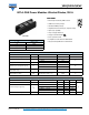
VSKCU300/06PbF Vishay Semiconductors INT-A-PAK Power Modules Ultrafast Diodes, 300 A FEATURES • Electrically insulated by DBC ceramic • 3500 VRMS isolating voltage • Standard JEDEC package • Simplified mechanical designs, rapid assembly • High surge capability • Large creepage distances • UL approved file E78996 INT-A-PAK • Case style INT-A-PAK • Compliant to RoHS directive 2002/95/EC PRODUCT SUMMARY IF(AV) at TC • Designed and qualified for industrial level 300 A at 48 °C VR 600 V trr (typical) 13
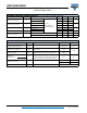
VSKCU300/06PbF INT-A-PAK Power Modules Ultrafast Diodes, 300 A Vishay Semiconductors DYNAMIC RECOVERY CHARACTERISTICS (TJ = 25 °C unless otherwise specified) PARAMETER SYMBOL Reverse recovery time trr Peak recovery current Irr Reverse recovery charge Qrr Peak rate of recovery current TEST CONDITIONS TYP. MAX. - 130 165 TJ = 125 °C - 195 260 - 11 18 - 20 30 - 670 1485 TJ = 125 °C - 1800 3900 TJ = 125 °C - - 400 IF = 50 A, TJ = 25 °C, dI/dt = 400 A/μs, VR = 200 V - 0.
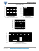
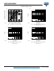
VSKCU300/06PbF Vishay Semiconductors 100 1000 IR - Reverse Current (mA) IF - Instantaneous Forward Current (A) INT-A-PAK Power Modules Ultrafast Diodes, 300 A TJ = 150 °C 100 TJ = 25 °C 10 0.5 1.0 1.5 2.0 2.5 3.0 3.5 VFM - Forward Voltage Drop (V) 93155_01 1 0.1 0.01 TJ = 25 °C 0.001 100 1 0 TJ = 150 °C 10 200 400 500 600 VR - Reverse Voltage (V) 93155_02 Fig. 1 - Maximum Forward Voltage Drop Characteristics 300 Fig. 2 - Typical Values of Reverse Current vs.
VSKCU300/06PbF INT-A-PAK Power Modules Ultrafast Diodes, 300 A Vishay Semiconductors 900 10 000 VR = 400 V 700 RMS limit 600 500 Qrr (nC) Average Power Loss (W) 800 D = 0.20 D = 0.25 D = 0.33 D = 0.50 D = 0.75 DC 400 300 200 1000 IF = 50 A, TJ = 25 °C 100 0 0 100 200 300 400 IF(AV) - Average Forward Current (A) 93155_05 100 100 500 Fig. 5 - Forward Power Loss Characteristics Fig. 7 - Typical Reverse Recovery Charge vs.
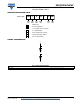
VSKCU300/06PbF INT-A-PAK Power Modules Ultrafast Diodes, 300 A Vishay Semiconductors ORDERING INFORMATION TABLE Device code VSK C U 300 1 2 3 4 1 - Module type 2 - Circuit configuration: / 06 PbF 5 6 C = 2 diodes common cathode 3 - U = Ultrafast diode 4 - Current rating (300 = 300 A) 5 - Voltage rating (06 = 600 V) 6 - PbF = Lead (Pb)-free CIRCUIT CONFIGURATION (1) + (2) (3) LINKS TO RELATED DOCUMENTS Dimensions Document Number: 93155 Revision: 18-May-10 www.vishay.
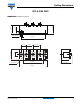
Outline Dimensions Vishay Semiconductors INT-A-PAK DBC 28 (1.10) 9 (0.33) 30 (1.18) DIMENSIONS in millimeters (inches) Ø 6.5 (Ø 0.25) 80 (3.15) 23 (0.91) 7 6 5 4 14.5 23 (0.91) (0.57) 35 (1.38) 17 (0.67) 1 2 3 66 (2.60) 37 (1.44) 3 screws M6 x 10 94 (3.70) Document Number: 95254 Revision: 11-Dec-07 For technical questions, contact: indmodules@vishay.com www.vishay.
Legal Disclaimer Notice www.vishay.com Vishay Disclaimer ALL PRODUCT, PRODUCT SPECIFICATIONS AND DATA ARE SUBJECT TO CHANGE WITHOUT NOTICE TO IMPROVE RELIABILITY, FUNCTION OR DESIGN OR OTHERWISE. Vishay Intertechnology, Inc., its affiliates, agents, and employees, and all persons acting on its or their behalf (collectively, “Vishay”), disclaim any and all liability for any errors, inaccuracies or incompleteness contained in any datasheet or in any other disclosure relating to any product.