
Instruction Manual

www.vishay.com For technical questions, contact: ind-modules@vishay.com
Document Number: 94422
4 Revision: 03-Jun-08
VSK.F200..P Series
Vishay High Power Products
Fast Thyristor/Diode and Thyristor/Thyristor
(MAGN-A-PAK
TM
Power Modules), 200 A
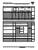
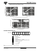
Note
• Table shows the increment of thermal resistance R
thJC
when devices operate at different conduction angles than DC
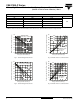
Fig. 1 - Current Ratings Characteristics
Fig. 2 - Current Ratings Characteristics
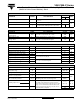
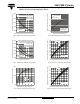
Fig. 3 - On-State Power Loss Characteristics
Fig. 4 - On-State Power Loss Characteristics
ΔR
thJC
CONDUCTION
CONDUCTIONS ANGLE SINUSOIDAL CONDUCTION RECTANGULAR CONDUCTION UNITS
180° 0.009 0.006
K/W
120° 0.10 0.011
90° 0.014 0.015
60° 0.020 0.020
30° 0.32 0.033
60
70
80
90
100
110
120
130
0 40 80 120 160 200 240
30°
60°
90°
120°
180°
Average On-state Current (A)
Maximum Allowable Case Temperature (°C)
Conduc tion Angle
VSK.F200.. Serie s
R ( D C ) = 0 . 12 5 K/ W
thJC
60
70
80
90
100
110
120
130
0 50 100 150 200 250 300 350
DC
30°
60°
90°
120°
180°
Average On-state Current (A)
Maximum Allowable Case Temperature (°C)
Conduction Period
VSK.F200.. Se rie s
R (DC) = 0.125 K/ W
thJC
0
50
100
150
200
250
300
350
0 40 80 120 160 200
RM S Li m i t
Conduction Angle
Maximum Average On-state Power Loss (W)
Average On-state Current (A)
180°
120°
90°
60°
30°
VSK.F200.. Series
Pe r Ju n c t io n
T = 1 2 5 ° C
J
0
50
100
150
200
250
300
350
400
450
500
0 50 100 150 200 250 300 350
DC
180°
120°
90°
60°
30°
RM S Li m it
Conduction Period
Maximum Average On-state Power Loss (W)
Average On-state Current (A)
VSK.F200.. Series
Pe r Ju n c t i o n
T = 1 2 5 ° C
J