
Instruction Manual

Document Number: 94422 For technical questions, contact: ind-modules@vishay.com
www.vishay.com
Revision: 03-Jun-08 3
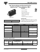
VSK.F200..P Series
Fast Thyristor/Diode and Thyristor/Thyristor
(MAGN-A-PAK
TM
Power Modules), 200 A
Vishay High Power Products
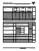
SWITCHING
PARAMETER SYMBOL TEST CONDITIONS
VALUES
UNITS
KJ
Maximum non-repetitive rate of rise dI/dt
Gate drive 20 V, 20 Ω, t
r
≤ 1 ms, V
D
= 80 % V
DRM
,
T
J
= 25 °C
800 A/µs
Maximum recovery time t
rr
I
TM
= 350 A, dI/dt = - 25 A/µs, V
R
= 50 V, T
J
= 25 °C 2
µs
Maximum turn-off time t
q
I
TM
= 750 A; T
J
= T
J
maximum; dI/dt = - 25 A/µs;
V
R
= 50 V; dV/dt = 400 V/µs linear to 80 % V
DRM
20 25
BLOCKING
PARAMETER SYMBOL TEST CONDITIONS VALUES UNITS
Maximum critical rate of rise of
off-state voltage
dV/dt T
J
= 125 °C, exponential to 67 % V
DRM
1000 V/µs
RMS insulation voltage V
INS
50 Hz, circuit to base, T
J
= 25 °C, t = 1 s 3000 V
Maximum peak reverse and off-state
leakage current
I
RRM
,
I
DRM
T
J
= 125 °C, rated V
DRM
/V
RRM
applied 50 mA
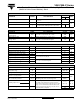
TRIGGERING
PARAMETER SYMBOL TEST CONDITIONS VALUES UNITS
Maximum peak gate power P
GM
f = 50 Hz, d% = 50 60
W
Maximum peak average gate power P
G(AV)
T
J
= 125 °C, f = 50 Hz, d% = 50 10
Maximum peak positive gate current I
GM
T
J
= 125 °C, t
p
≤ 5 ms
10 A
Maximum peak negative gate voltage -V
GT
5V
Maximum DC gate current required to trigger I
GT
T
J
= 25 °C, V
ak
12 V, Ra = 6
200 mA
DC gate voltage required to trigger V
GT
3V
DC gate current not to trigger I
GD
T
J
= 125 °C, rated V
DRM
applied
20 mA
DC gate voltage not to trigger V
GD
0.25 V
THERMAL AND MECHANICAL SPECIFICATIONS
PARAMETER SYMBOL TEST CONDITIONS VALUES UNITS
Maximum junction operating
temperature range
T
J
- 40 to 125
°C
Storage temperature range T
Stg
- 40 to 150
Maximum thermal resistance,
junction to case per junction
R
thJC
DC operation 0.125
K/W
Maximum thermal resistance,
case to heatsink per module
R
thC-hs
Mounting surface flat, smooth and greased 0.025
Mounting torque ± 10 %
MAP to heatsink
A mounting compound is recommended. The torque
should be rechecked after a period of 3 hours to
allow for the spread of the compound. Use of cable
lugs is not recommended, busbar should be used
and restrained during tightening. Threads must be
lubricated with a compound.
4 to 6
(35 to 53)
N · m
(lbf · in)
busbar to MAP
Approximate weight
500 g
17.8 oz.